Category Archives: Installation

Sensors Monitoring – Envinronment Setup 2

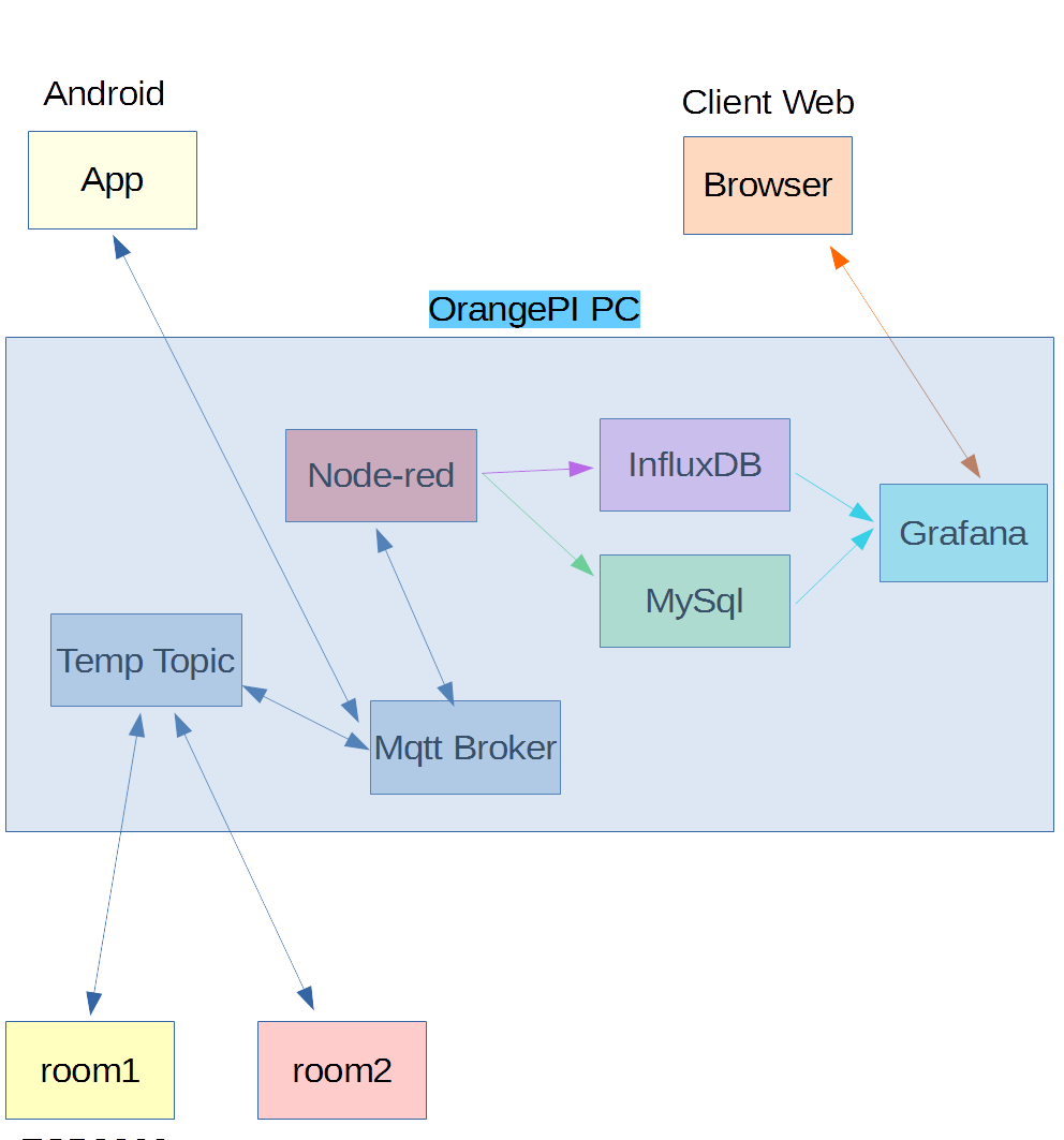
After the software components installation in the previous article

Sensors Monitoring – Eninronment Setup

we finish this operation with this article.

Infludb

The Influxdb is installed as indicated in the link

Influxdb

For Debian 9 we execute the following commands

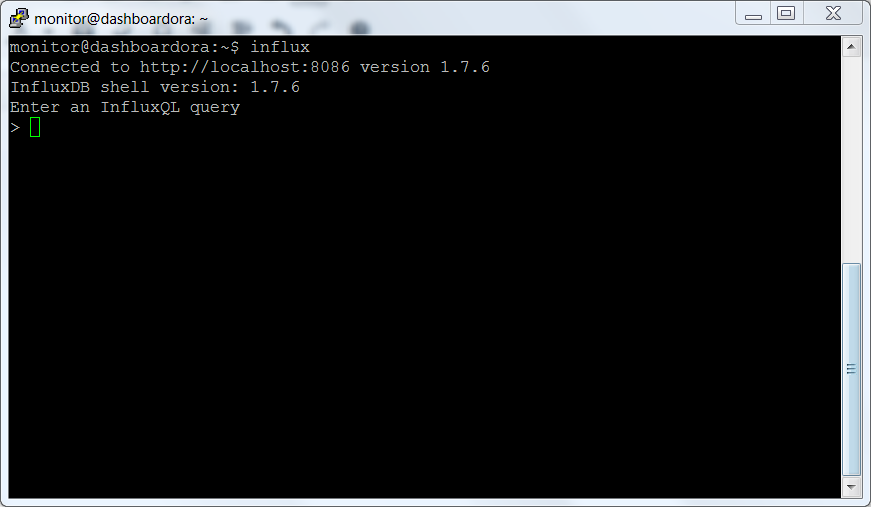
Check that everything works correctly by connecting with the infludb client

infux

Nodered

We proceed to the installation of node.js

Then we proceed to  nodered installation, as indicated at the link

Nodered installation

To run nodered at the start up, we use the script available at the following link

Nodered autostart

We did not run the automated script, but executed the following steps

Edit /etc/init.d/nodered and change the user from pi to monitor, ie change the parameter

in

Run

Start  nodered

Check that nodered works by accessing the following link with the browser

http://dashboardora.local:1880

nodered

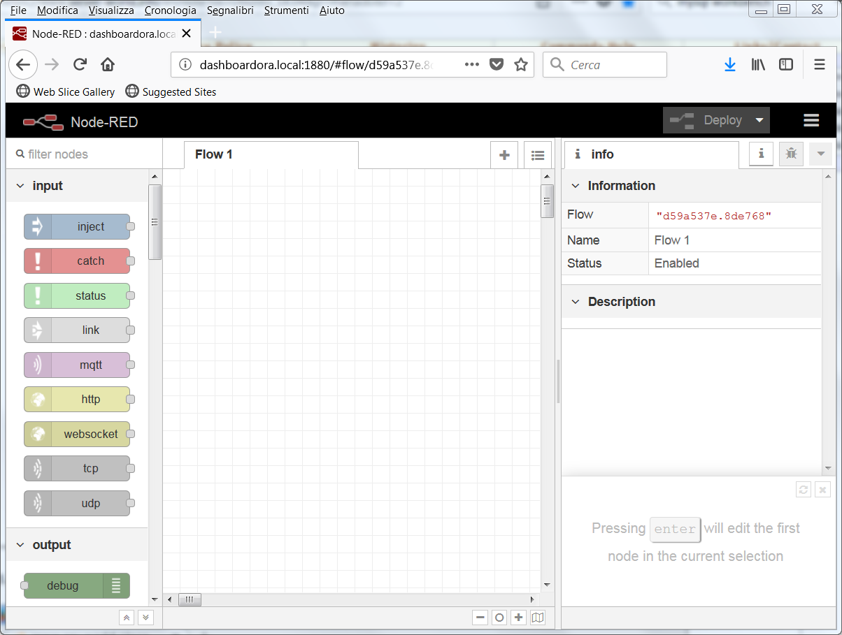
Restart the system and check that nodered starts automatically.

Proceed to the installation of the nodered add-ons


Grafana

We proceed to download the version for arm

Grafana for ARM

Enable and start Grafana

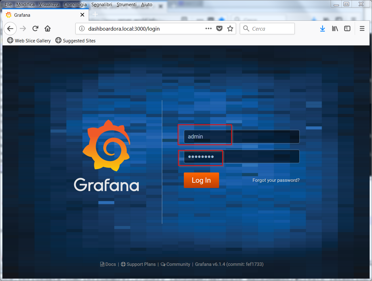
Access the system using the url

http://dashboardora.local:3000

Log in with the user admin and password admin; change the password

GrafanaOnce the new password has been set, the setup interface is available

Grafana2
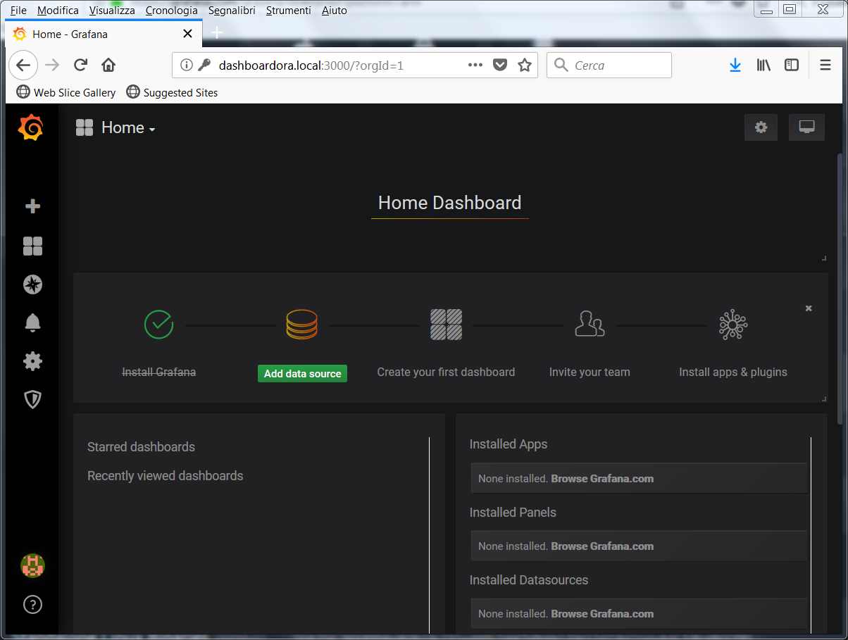
In the next articles we will execute the settings to be able to view the sensors data.

Reverse Proxy installation

To access the system through port 80 of the http server we use nginx as a reverse proxy
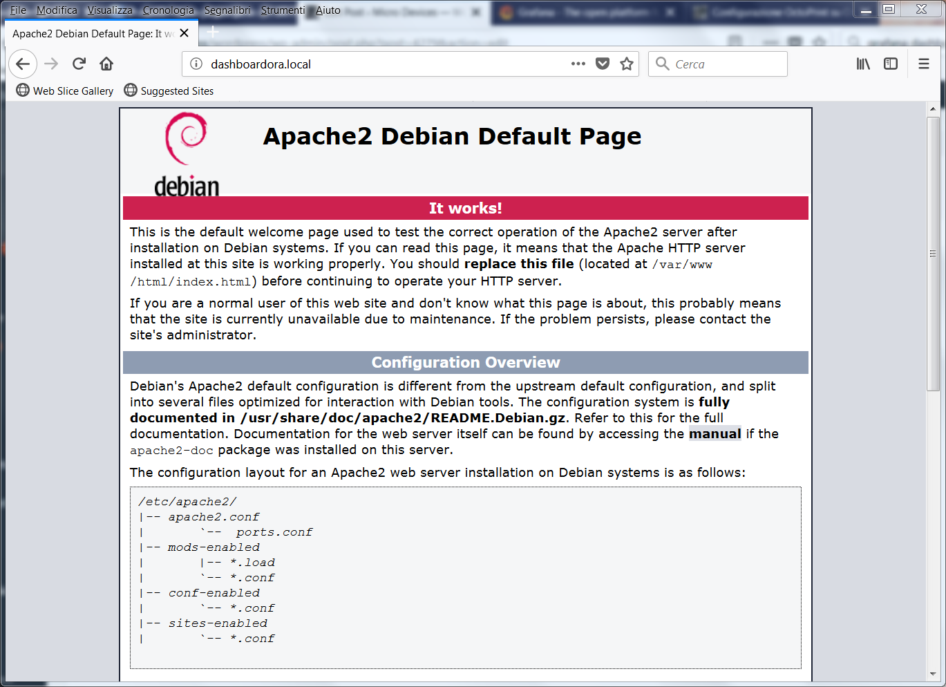
nginx

We disable apache

We proceed to the installation of nginx

Everything must be configured to access the two systems using the following links

http://dashboardora.local/nodered for nodered

http://dashboardora.local/grafana for grafana

For Grafana we follow the official documentation

Grafana proxy

We change the file /etc/grafana/grafana.ini by modifying the domain and root_url parameters; in our file the parameteres are modified  as follows

Then we configure nginx, creating the servizi file with the following contents in the /etc/nginx/sites-available folder

Here is the link of the nginx configuration

nginx configuration

We run the following command

and start nginx and grafana services

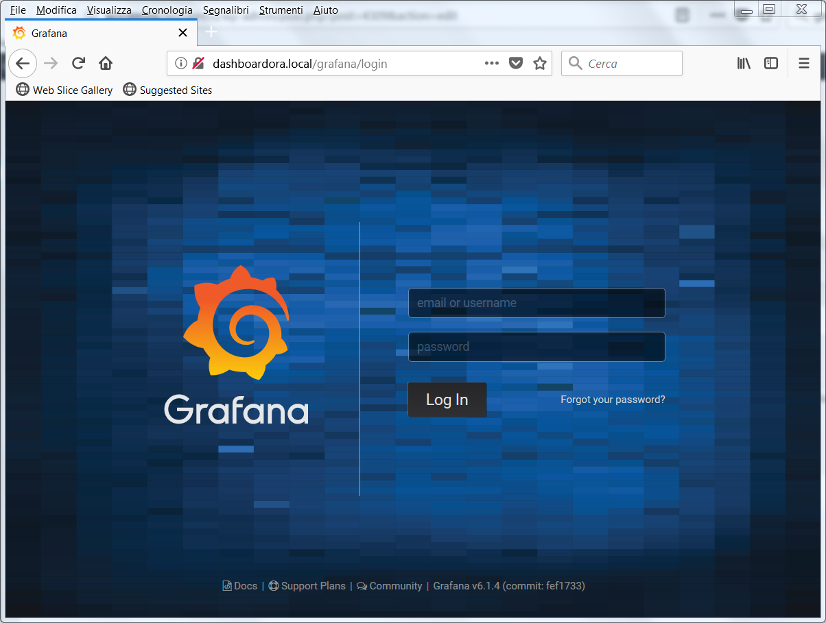
At this point it is possible to access the two services via the links

http://dashboardora.local/nodered

nodered-nginx

http://dashboardora.local/grafana

grafana-nginxIn the next article we start the configuration of the various modules needed for the sensors monitoring

Sensors Monitoring – MySql Configuration

Sensors Monitoring – Envinronment Setup

In setting up the infrastructure for monitoring sensors made up of ESP8266 devices in previously published articles

Mqtt with Beaglebone ed ESP8266 – Freeboard

Freeboard had been set up to display the data coming from the sensors.

In this new series of articles, we  set up Grafana

Grafana Dashboard

as  environment to view the data of the various sensors.

We implement the environment, in this case,  on an Orange Pi PC board, but other arm or pc system can be used.

Below the architecture used in this series of articles

archGrafana

In these articles we’ll use the maximum authorizations for each environment, we will not use authorizations on mosquitto and no encrypted connections will be used. In a test environment this setting is fine, but in an operating environment it is necessary to set up the correct authorizations and possibly the encryptions in the connections in all environments.

We have installed our compiled version of Debian 9 Stretch for Orange PI PC. The image used is the following

Image Download

The monitor user was created during the Image setup, while the hostname was renamed in dashboardora. If not installed proceed to install the avahi daemon

In this way the services can be accessed by publishing the hostname, i.e. dashboardora.local.

Using the armbian utilities  disable ip6 on the system; to carry out this setting launch armbian-config

ipv6Disable1Proceed to diasble IPV6

ipv6Disable2

As a first step we install the  mqtt broker mosquitto

Install the http services and the databases Mysql and MySqlWorkbench

Apache2

and various prerequisites

Start apache

and check that the server responds to the web address, which in our case corresponds to http://dashboardora.local

apache

MySql

Debian 9  comes with MariaDB; you must set the password for the database administration user root with the following command

We set the root password and the ability to log in from other hosts as root

mariadb-secureThe other chosen options are listed below

mariadb-secure2

We install phpmyadmin for database management

At the next screen choose apache2

phpmyadminFinally choose NO

phpmyadmin1

Run the commands listed below

Check that the system works correctly by accessing via web browser by adding to the apache phpmyadmin address, in our case

http://dashboardora.local/phpmyadmin

phpmyadmin2

Log in with the database root credentials.

Mariadb must be enabled to accept connections from other hosts. To do this, go to the folder

and edit the 50-server.cnf file as root, changing the setting

in

To allow the root database user to be able to access from an external client, it is necessary to log on mariadb locally with his client and enable this option; therefore the following is performed


Mysql Workbench Installation on PC

Go to the following link

MySql Workbench

and download the version for your operating system; proceed with the installation.

For Linux the package is also available in the distribution repositories.

After configuring the connection, you access the MySql system control screen.

MySQLWorkbenchIn the next article we will continue the installation of the other components to be able to monitor the sensors

Sensors Monitoring – Envinronment Setup 2

Micropython – Development tools Ampy – Eric

After the  uPyCraft  intallation in the previous article

MicroPython – IDE MicroPython uPyCraft

let’s now look at other tools available for the development in MicroPython for various platforms.

This article shows the operations to be performed on Windows and Linux.

First Python package to install is Ampy (Adafruit MicroPython Tool)

ampy

The tool is available in the python repositories, so it can be installed using the  pip tool.

In Windos run in a dos command prompt

Similarly in Linux run in a shell

The available commands are listed running

ampyAmpy allows the transfer, creation, viewing, and execution of files on the device.

As for the IDE you can install Eric, generic Python IDE

Eric

Eric does not allow communication from the IDE with the device as seen with uPyCraft; this task is delegated to Ampy. For the installation proceed as follows:

  • For Linux Debian 9 just run

The tool is available among the development tools; at the first execution it requires default settings

ericSettingsWe define the workspace location

ericWorkspaceand we have the access to the IDE

eric

  • For Windows download the zip

Eric

Unzip the zip into a folder from which we run it; install the prerequisites

Perform the eric installation at this point by double clicking on install.py

ericInstallWindowsThe program checks the prerequisites and completes the installation

ericWindowsProcedure

Clicking twice on eric6.py or running eric6 from a dos command prompt we run the program in the same way as seen for Linux Debian

ericWindows

In the next article we will briefly examine how a MicroPython program is structured

MicroPython – MicroPython program structure


Micropython – MicroPython IDE uPyCraft

After installing the firmware on the Nodemcu esp8266 DevKit board

MicroPython Firmware

let us now examine a development tool can be suitable for the development of Python code.

A tool that allows both to write code and upload it to the device is uPyCraft

uPyCraft

The tool currently works for Windows and from version 0.30 is also available for Linux; the source code is available at the link

uPyCraft Source

Here are the steps for Windows and Linux.

  • Windows

Once downloaded the package we must  run it as an administrator; the installation of the Monaco font is required

monaco-font

After the font installation,  we have the access to the IDE

upycraft-v0-29We set the Location in Tools->Preferences->Language Location

upycraftlocation

and the serial port paramenters in Tools->Preferences->Serial

upycraftserialsettingsWe plug the device into an USB port and set the serial port on uPyCraft

upycraftserialWe choose the device type; in this case it is ESP8266

upycraftdeviceBy clicking on the connection icon we access to the device and view the files on it

upycraftconnectionThe firmware installation expands on the device only the Python file boot.py

upycraftfilesystemThe tool allows to download examples of MicroPython code for the board, blink.py for example

examplesClicking the “Download and Run” button we load the code onto the device and run it

blinkIn this example the led of the Nodemcu DevKit blinks.

  • Linux

The tool is similar in the Linux version; once downloaded the package to which we have to assign  the execution right we run it. We must assign to the user the access to the serial port with the command, already seen above

In our case, on Debian 9, we have the following screens similar to what we saw on Windows.

In the uPyCraft IDE

upycraft-v0-30linuxWe set the Location in Tools->Preferences->Language Location

upycraftlocationlinux

and the serial port paramenters in Tools->Preferences->Serial

upycraftserialsettingslinuxWe plug the device into an USB port and set the serial port on uPyCraft

upycraftseriallinuxWe choose the device type; in this case it is ESP8266

upycraftdevicelinuxBy clicking on the connection icon we access to the device and view the files on it

upycraftconnectionlinuxThe firmware installation expands on the device only the Python file boot.py

upycraftfilesystemlinuxThe tool allows to download examples of MicroPython code for the board, blink.py for example

exampleslinuxClicking the “Download and Run” button we load the code onto the device and run it

blinklinuxAs in Windows the led of the Nodemcu DevKit blinks..

In version 0.30 for Windows we noticed some bugs, so for this operating system we continue to use the uPyCraft  version 0.29.

Further informations about uPyCraft can be found at the following site

uPyCraft Documentation

In the next article we will discuss another Python development tool

MicroPython – Development tools Ampy – Eric

MicroPython – Python on embedded devices

In this article we begin to treat MicroPython

MicroPython

an implementation of Python3

Python

for embedded devices.

Various images are available on the MicroPython website for different devices, including the modules esp8266 and esp32

MicroPython Dowloads

We start our tests with a Nodemcu esp8266 DevKit

Nodemcu Devkit

We proceed to load the firmware  on this card.

The Micropython site also refers how to load the firmware on the cards; these informations are available at the link

MicroPython Tutorial for esp8266

To load the firmware we always use the tool esptool, also available on the Python repository.

To be able to use it, we need to install Python3 on our development platform. Here are the steps to follow for Windows and Linux.

  • Windows

For windows we must first install the Python3 environment, available at the following link

Python for Windows

In our case, we downloaded the  version 3.6.4 for 64-bit systems. We installed the package  with administrative rights

setuppythonAfter proceeding to add Python in the Path we click “Install Now”

pythonsetupendAfter the installation, we open a dos command propmt and check the installed Python version

pythonversionAlways from the dos command prompt we proceed to the installation of esptool with the command

esptoolinstallationAt this point we can proceed to the MicroPython firmware upload on the Nodemcu esp8266 DevKit. Of course, it is necessary to have the serial-ttl drivers installed for your DevKit model on Windows. Now go into  the folder where the firmware has been downloaded  and run the following  commands from the dos command prompt

erase_flashProceed to load the firmware

firmware_flashOnce the firmware is installed  we log on the Python console using, in our case with the nodemcu card DevKit, the same port already used to load the firmware.

On Windows we can use Putty

Putty

and set the serial connection to 115200 baud rates

repl_putty

  • Linux

For Linux we use the Debian 9 distribution, but the procedure can be extended to other distributions. After installing Debian 9 , similar to version 8

Debian 8

we proceed to the installation of Python3 and esptool from a Linux shell

Add the user used on Debian to the dialout group

In our case, using  sviluppo as a user, the command is as follows

Let’s move on to install the Python esptool package

We can then proceed with the installation of the firmware in the same way as done on Windows.

We check on which serial port the card is available (ttyUSBX)

ttylinuxWe perform a flash erase and firmware upload

To log on the DevKit we use screen

Here is the manual of the tool

Screen Manual

To detach from screen press

instead to resume run

To quit screen

Once connected you get the same result as Windows

screenIn the next article we will begin to see which IDEs can be used to create and load our Python code

MicroPython IDE uPyCraft


OctoPrint installation on Orange PI PC – Python package installation

This article describes how to enable the Orange PI PC board to work as 3d printers network server.

A  software that provides this functionality is OctoPrint

OctoPrint

From the OctoPrint site we can download an image for Raspberry PI with the system already ready; in the case of the Orange PI PC we have  to install and configure OctoPrint on a Linux image.

You can also use a Linux image available for Orange PI PC and run the steps related to OctoPrint package installation, but you have to check the prerequisites for Octoprint python package installation.

We instead built for this article an image using the Armban scripts.

As a first step, prepare the micro sd card with an Armbian image. In the specific case, we’ll use a Debian Jessie image created using the Armbian script, as indicated on the link

Armbian building

and described also in a previous article

Building Armbian image for Orange PI PC

We followed these steps to build the Armbian image on Ubuntu Xenial 16.04; from  a Linux command shell

In the building options choose

armbianopipcfosWe selected the default kernel configuration

armbianopipckernelChoose an Orange PI PC board

armbianopipcboardWe used the mainline kernel

armbianopipcmlkerneland Debian Jessie as distribution

armbianopipcjessieWe built an image with desktop envinronment

armbianopipcjessiedeAfter this option, the script proceeds to the compilation. The generated image is Armbian_5.34_Orangepipc_Debian_jessie_next_4.13.12_desktop.img. This image can be downloaded from the link

Armbian image for Orange Pi PC

Start Armbian and create the user for the Jessie image; in this case we choose octoprint/password as user.

If necessary, reconfigure the keyboard with the command

and proceed to upgrade the system

If the system needs to be configured via a wireless connection, the connection must be active at startup. For this purpose in our case we used the Wicd daemon

Wicd Debian

Remove the network-manager package

This command uninstalls network-manager and network-manager-gnome.

Check that the wireless interface is not present in

/etc/network/interfaces

Proceed to Wicd installation

Check that the octoprint user is present in the netdev group

In our case it is already present, giving as a result

netdev-group

If not present, add it with the command

Start  wicd

Logon to the armbian graphic desktop and start the wireless configuration with the command

wicd-client

Configure and save the network connection from the graphical interface.

If you want the remote desktop follow the steps listed in the article

Remote desktop setup for Armbian on Orange PI PC

We can now install Octoprint. Follow the steps available at the link

OctoPrint installation on Linux

Install the prerequisites

Create under /opt the octoprint folder and assign the ownership  to octoprint

In a Linux shell command go to /opt/octoprint  folder and download the software

Run

Create the  .octoprint folder

Add  octoprint to the following groups  to manage the 3d printer using the USB port

Check  the correct installation by running the command

The OctoPrint server can be reached on port 5000 at the IP address of Orange PI PC

http://ipaddress:5000

octoprinttest

Install the Cura Engine at this point; place yourself in the octoprint user’s home and download the source package

Unpack the package

Go into  the unpacked folder

Run  the compilation with the command

The compiled software is located under the build folder

curaengineCreate the /opt /octoprint/cura folder and copy the CuraEngine file to this folder

The executable is now in the /opt/octoprint/cura folder and will be used later by OctoPrint.

In the next article we’ll treat how to configure OctoPrint’s automatic startup

OctoPrint Autostart

Installation and configuration of Lede image on Linkit 7688 Duo

After you have attached to the board the support devices,  as specified in the previous article

Linkit 7688 Duo Connections

and built the image

Lede Image for Linkit 7688 Duo

we upload the image to the device.

Following the documentation availble at the link

Update the firmware with a USB drive

to update the firmware copy the lede-ramips-mt7688-LinkIt7688-squashfs-sysupgrade.bin file to the root directory of a FAT32 USB drive and rename it as lks7688.img.

Attach, now,  the USB drive to the HOST port of the board with an OTG cable and follow the steps

  1. Press and hold the on-board WiFi button.
  2. Press the MPU reset button once, while holding the WiFi button.
  3. Keep holding the WiFi button for about 5 seconds. Do not release until the orange LED for WiFi is off.  DO NOT press the WiFi button longer than 20s or it will upgrade the bootloader.
  4. The device will automatically reboot after firmware update is complete.

aggiornamento7688duo

You can control the operation via the USB TTL serial connected to the PC and activated on the enabled Com port  with the following settings

  • Port:  Enabled COM
  • Speed: 57600
  • Data Bits: 8
  • Stop Bits: 1
  • Parity: None
  • Flow Control: XON/XOFF

putty-configurationUse, for example, putty to connect, press Enter if the screen is not active,  and to check the steps the system is runnig when upgrading

aggiornamento

When the orange LED starts blinking at a lower frequency the card is ready to be used

On the Lede system, the wireless card is disabled by default, while Lan is operational, but only accessible via a Breakout board

Linkit Breakout

To enable the wireless card connect with putty (screen on Linux) to the previously connected USB TTL serial and  go to the /etc/config folder; edit the network file and add at the end the following section

Save and run

Edit the wireless file and add at the end the section

where Access Point and password indicate the Access Point name and password; the wireless security setting is wpa2.

Save and run

Enable the wireless, running

Access the Lede interface with the address assigned by the Access Point

lede-luciSet the password and access to the Lede management.

In this firmware, the leds on the board  are not synchronized with wireless operations, unlike from OpenWrt firmware with the Mediatek proprietary interface and drivers.

In the next article, we will give some examples of interfacing with the arduino IDE,  based on the tutorial on the Mediatek site using this custom Lede  image

 LEDE on Linkit 7688 Duo – MPU-MCU Uart communication

Installation and configuration of the Openwrt Image on Linkit 7688 and 7688 Duo

After you have attached to the board the support devices,  as specified in the previous article

Linkit 7688 Duo Connections

and built the image

OpenWrt building for Linkit 7688 and 7688 Duo

we upload the image to the device.

Following the documentation availble at the link

Update the firmware with a USB drive

to update the firmware copy the openwrt-ramips-mt7688-LinkIt7688-squashfs-sysupgrade.bin file to the root directory of a FAT32 USB drive and rename it as lks7688.img.

Attach, now,  the USB drive to the HOST port of the board with an OTG cable and follow the steps

  1. Press and hold the on-board WiFi button.
  2. Press the MPU reset button once, while holding the WiFi button
  3. Keep holding the WiFi button for about 5 seconds. Do not release until the orange LED for WiFi is off.  DO NOT press the WiFi button longer than 20s or it will upgrade the bootloader.
  4. The device will automatically reboot after firmware update is complete.

aggiornamento7688duo

You can control the operation via the USB TTL serial connected to the PC and activated on the enabled Com port  with the following settings

  • Port:  Enabled COM
  • Speed: 57600
  • Data Bits: 8
  • Stop Bits: 1
  • Parity: None
  • Flow Control: XON/XOFF

putty-configurationUse, for example, putty to connect, press Enter if the screen is not active,  and check the steps the system is runnig when upgrading

aggiornamento

When the orange LED starts blinking at a lower frequency the card is ready to be used.

Search for visible access points from your PC  and you should find an access point named LinkIT_Smart_7688_xxxxxx, where xxxxxx identifies the specific device.

Connect to this Access Point and access via browser at 192.168.100.1 or at mylinkit.local if you have satisfied the prerequisites

Getting started

collegamentolinkitEnter a password and access the next step

collegamentolinkit2Select OpenWrt for Advanced Configuration

collegamentolinkit3Set the password on OpenWrt

collegamentolinkit4entering it twice

collegamentolinkit5At this point, the system is configured as an Access Point. In our case, we wanted to set the Link 7688 Duo as a client of an Access Point with WPA2 security. To get this setting, if you have a visible network, go to the Network section of the main web console interface

accesso_linkit-smart_network1set the values for the Access Point and restart the system

accesso_linkit-smart_network2

If the Access Point is hidden, you should set the parameters directly in the configuration files in /etc /config.

Connect with putty to the previously connected USB TTL serial and  run the commands for Access Points with wpa2 security

 Save the settings

and activate the new configuration

Check the /etc/config/wireless file; you should see the addition of a new section, config wifi-iface ‘ap’,  to connect the board  to the access point

Now the card acts as a client and you can access it using the address released by the Access Point or by name as indicated by the documentation

Getting started

accesso_linkit-smartIn the next article, we’ll install and configure  the custom Lede firmware

Installation and configuration of Lede image on Linkit 7688 Duo

Debian sd card setup for Beaglebone Black

In the previous article we started up the development board Beaglebone Black / Green.

Startup of the Beaglebone

Let’s look  how to install an updated image of Debian for BeagleBone. As a first step we have to access the site which contains the Beaglebone  images

Beaglebone images

We download, having a BeagleBone Black Rev. C, bone-debian-8.6-lxqt-4gb-armhf-2016-11-06-4gb.img.xz. Unpack the 7zip image and load into a micro sd card with Win32DiskImager, as done for the Orange PI PC

SD card setup for Orange PI PC

If we wanted to load that image on the internal flash, we must edit the /boot/uEnv.txt files on a Linux system and uncomment the line

In that case, when we start the board the system will rewrite the operating system present on the internal flash with the version loaded on the micro sd card. We do not follow this road in order to do all the tests on the sd card leaving the internal partition unmodified. So let’s connect our Beaglebone to a network router. We insert the micro sd card and startup the development board. In some boards we need to press of the USER / BOOT button

 beaglebone black

because the operating system boots from micro sd card; with our board it is not necessary to perform this operation. We have to log on Beagleone now; the avahi-daemon service is already active on the Beaglebone and Linux systems resolve the address by hostname; Windows, instead, needs tha samba service activated to solve the Beaglebone hostname; installing samba we obtain the hostname recognition with the protocol netbios from Windows. If you are using a Windows machine to work with the Beagelbone you must first check the ip assigned by the network router to the  BeagleBone. From a Linux system, for example, connect to the Beaglebone using ssh as debian / temppwd and the beaglebone hostname

ssh BeagleboneIn Windows we need to install the samba service first to have the same functionality. Proceed at this point with the updating and samba installation

After the updates and samba services activation, we are ready to show examples with our BeagleBone and we are able to connect to it using the beaglebone and beaglebone.local hostnames. In the next article we will see tools already available on the board and how to add more features.

We can install the ftp service too, as we could use it in next articles

 To deactivate and activate it use the following commands

Libreelec Image for Amlogic socs

In the market there are several TV boxes equipped with Android. Among the most common there are those based on soc Amlogic. For devices with this module there is the way to run, even in parallel without removing the Android image, a media center system based on Linux and Kodi, which is Libreelec. It is a fork of the mediacenter OpenELEC system

Libreelec

The supported platforms are similar to those already available for OpenELEC, but the community is carrying out the development of other images besides the official ones; this is the case for the Amlogic platform.

In Libreelec forum developers have developed unofficial images for tv boxes with soc Amlogic S802 / S905 / S905X

Amlogic Libreelec Forum

We’ll install a Libreelec image for an Amlogic S905 box, in our case the box is Android Beelink MiniMX III. The box comes with on board an Android firmware on the internal flash. The next steps allow to keep the Android firmware of the internal flash and Libreelec on the micro sd card. These instructions can be repeated at least in part with other boxes with soc Amlogic. Refer to Libreelec forum for more insights.

The first operation is to download the image from the link given on Libreelec forum

Amlogic S905 Libreelec Images

We download the version 7.0.2.007

Libreelec S905 7.0.2.007

At the link above there also the dtb files, device tree file, file containing the specifications of the hardware system, for different boxes already  tested.

We unzip the file and load it on a micro sd card in a similar way to what was done for the creation of OpenELEC image for the Orange IP PC

Openelec installation on Orange PI PC

Again we launch Win32DiskImager and after unpacking the LibreELEC-S905.aarch64-7.0.2.007.img.gz file we proceed to the writing on the micro sd card.

At this point,we insert the micro sd card into the box  that we start holding down, in the case of this model, the reset button on the bottom of the box. This is a one-time process; to subsequent reboots the system starts Libreelec, if there is the Micro SD card, or Android system, present on the internal flash, in the absence of micro sd card.

The image automatically uses the remote.conf file for the remote control  from the Android image intalled in the internal flash.

The configuration steps are quite similar to what was done for OpenELEC Orange PI PC, such as to enable the ssh daemon, etc; in this case the remote control, being a box supported by the image, is already working.

libreelec

 WARNING: The image installation on the device is at your own risk. We accept no responsibility if the installation leads to  malfunction or block of the device. Before performing any operation, make sure that you have the original image of the box so you can recover the Android system in case of issues.

In the next article we will see how to configure an infrared remote control with NEC protocol on a system based on soc Amlogic

Remote control configuration for Libreelec on Amlogic socs