Category Archives: Software

Cross building for Beaglebone

In the article on the Debian environment we prepared the linux machine for the development of embedded systems

Debian development envinronment

In the article on building an image for the Orange PI PC we installed the cross build tools for armhf environment

Building Armbian for Orange PI PC

Starting from the clean image of the Debian envinronment we list the steps required to install the cross compiling environment. We log on Debian Desktop as sviluppo/ password.

As a preliminary step we install  the cross toolchains in Debian

https://wiki.debian.org/CrossToolchains

Create the file crosstools.list in the /etc/apt/sources.list.d folder

and add the line

Save the file and add the key of  the repository embedian.org

Install the following packages and add the armhf architecture

We install at this point the Eclipse IDE for Cpp downloading the IDE for Linux 64bit

Eclipse IDE

Unzip the eclipse package under / home /sviluppo.

Install the jre java

Add the line at the end of the file

Run the following commands

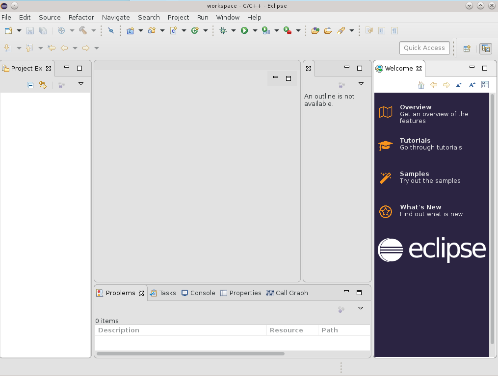
Run Eclipse from the eclipse folder to start the IDE

eclipse
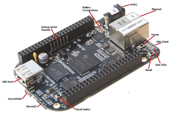
As a first example we create a simple program in C for BeagleBone.

Create a new project in C, by inserting the following data

new project
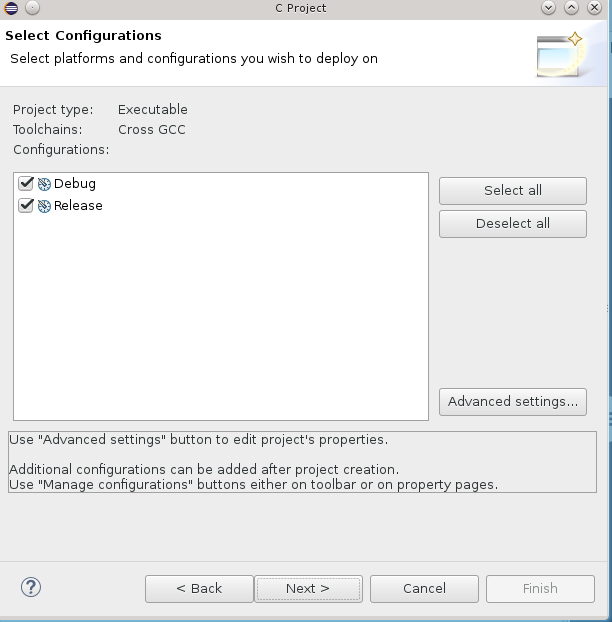
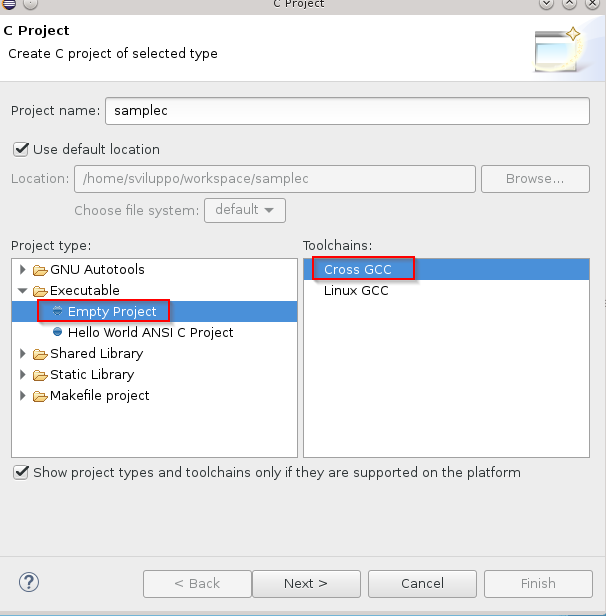
Select both configurations

project configurationEnter the cross compiler prefix and path

crosscompiler prefixPress Finish.
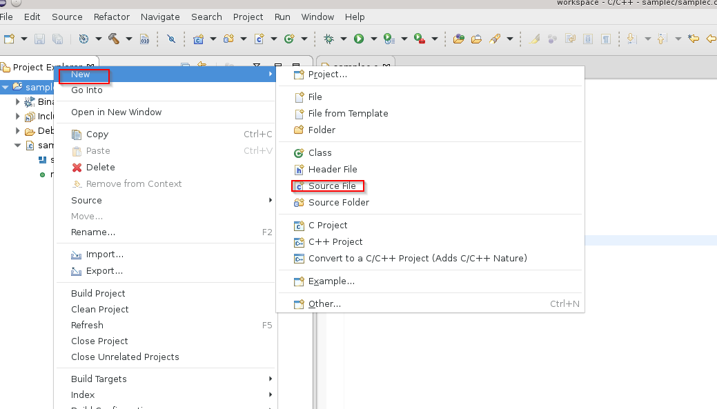
Add to the project a source file in C

C source fileInsert the following simple code

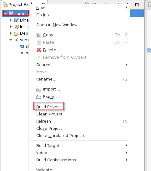
Proceed with the build by selecting the project with the right mouse button and choosing Build Project

project build 
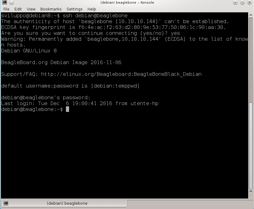
Transfer the generated files on BeagleBone. You can use scp or ftp.

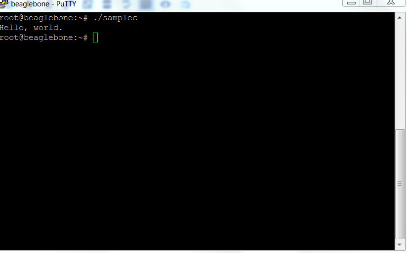
Give execution permissions to the file and run it

The result is of course the text inserted in the code

sample run

Development tools on Beaglebone

In the previous article we have installed and updated to the latest Debian image our BeagleBone

Debian sd card setup for Beaglebone Black

We also enabled the network services to access the board using the hostname.

After these changes we can access the Beaglebone using the following address in the the browser

http: //beaglebone.local

The web interface presents several examples of code executed with bonescript, javascript library based on node.js framework

Node.js

You can perform these simple examples to begin to interact with the board. There are also links to the development tools such as Cloud9, Nodered and informations about these development tools

toolsClicking on Cloud9 we access at the section dedicated to this tool. It is shown how to create a simple example and to run at boot the code placing it into the autorun folder in the IDE interface. From this section we can access to the Cloud9 ide available on port 3000 of the Beaglebone site

Cloud9

For more information about the tool, refer to the site

Cloud9

Accessing to the Nodered section we find  the link  to the web page about the basic informations about Nodered

Getting stared with Nodered

and the link to the Nodered ide, running at 1880 port of the web server running on BeagleBone

Beaglebone Nodered

Nodered beaglebone

In the web page about the first steps for Nodered there are examples with which to start using the tool. From the web site https://nodered.org we can have more informations about the tool.

In addition to tools in javascript on BeagleBone there are C/C++ compilers, Python interpreter and the possibility  to add additional development tools.

From the home page of the our BeagleBone board web interface, http: //beaglebone.local, we find the informations about all available headers and functions. The following image shows the  expansion headers

cape headers

In next articles we will show some code examples with the development board.

Debian sd card setup for Beaglebone Black

In the previous article we started up the development board Beaglebone Black / Green.

Startup of the Beaglebone

Let’s look  how to install an updated image of Debian for BeagleBone. As a first step we have to access the site which contains the Beaglebone  images

Beaglebone images

We download, having a BeagleBone Black Rev. C, bone-debian-8.6-lxqt-4gb-armhf-2016-11-06-4gb.img.xz. Unpack the 7zip image and load into a micro sd card with Win32DiskImager, as done for the Orange PI PC

SD card setup for Orange PI PC

If we wanted to load that image on the internal flash, we must edit the /boot/uEnv.txt files on a Linux system and uncomment the line

In that case, when we start the board the system will rewrite the operating system present on the internal flash with the version loaded on the micro sd card. We do not follow this road in order to do all the tests on the sd card leaving the internal partition unmodified. So let’s connect our Beaglebone to a network router. We insert the micro sd card and startup the development board. In some boards we need to press of the USER / BOOT button

 beaglebone black

because the operating system boots from micro sd card; with our board it is not necessary to perform this operation. We have to log on Beagleone now; the avahi-daemon service is already active on the Beaglebone and Linux systems resolve the address by hostname; Windows, instead, needs tha samba service activated to solve the Beaglebone hostname; installing samba we obtain the hostname recognition with the protocol netbios from Windows. If you are using a Windows machine to work with the Beagelbone you must first check the ip assigned by the network router to the  BeagleBone. From a Linux system, for example, connect to the Beaglebone using ssh as debian / temppwd and the beaglebone hostname

ssh BeagleboneIn Windows we need to install the samba service first to have the same functionality. Proceed at this point with the updating and samba installation

After the updates and samba services activation, we are ready to show examples with our BeagleBone and we are able to connect to it using the beaglebone and beaglebone.local hostnames. In the next article we will see tools already available on the board and how to add more features.

We can install the ftp service too, as we could use it in next articles

 To deactivate and activate it use the following commands

Startup of the Beaglebone development board

In a previous article we have given a brief description of Beaglebone Black board and its variants.

 Beaglebone development board

The BeagleBone in this review comes with 4GB of space on board, and with the operating system already installed.

We can access the BeagleBone, in our case the Black, without using the Ethernet network, but connecting it to a PC through the mini service USB connection as specified on the BeagleBone site

Getting started with Beaglebone

After connecting the BeagleBone Black to the PC via the USB cable we find  another removable  device to the existing disks

Beaglebone removable diskRunning start.htm we start an interface similar to the one available on  the  getting-started web site

getting startedWe proceed to the installation of network-over-USB drivers for the  operating system, Windows 64-bit in our case

driver network over usbProceed to download the file and run it, providing the permissions required by Windows

beaglebone driver installerAt the end the window with the performed operations is shown

beaglebone driver installer summaryUsing Firefox or Chrome we access to the following address http://192.168.7.2; we access in this way to the web server, running on Beaglebone board, through network over  USB

beaglebone web siteThe page shows how to update the system, login to the IDECloud9, perform various  Bonescript examples.

The access to the Cloud9 IDE

Cloud9 IDE Informations

takes place on port 3000 to the IP address specified above, ie http://192.168.7.2:3000

cloud9 ideIn our examples, we will not change the operating system present on the internal eMMC card but we will download an updated version of Debian for BeagleBone and will install it on a micro sd card.

The system can be closed  using  the Power button on board

power buttonor by connecting via ssh at 192.168.7.2 address with the debian user ,using temppwd as password, and executing the command “sudo poweroff”

sshIn the next article we will proceed to download and install on a micro sd card the last Debian image for BeagleBone

Debian sd card setup for Beaglebone Black

Openelec addon building for Orange PI PC

In the article about the OpenELEC build for Orange PI PC

Openelec building for Orange PI PC

we created the environment and compiled the OpenELEC image for our development board. We integrate what it has been said in the previous article showing how to build  the Openelec addons for our Orange PI PC board.

As stated in the linked article we have to open a shell command window in the  OPENELEC-OPIPC folder

Using the  graphical interface in Debian we can verify the availabilty of the official addons structure. To add the unofficial ones we have to run from the  OpenELEC-OPIPC folder

Now we proceed to build an official addon and an unofficial one. The packages that you can build ara available in the official folder as shown below

official Addonsand in the unofficial folder

unofficial Addons

We build the  official pvr.iptvsimple addon with the command

For the unofficial we build the p7zip module

The compiled addons are availablein the following folder

addons

In the case of errors in the compliation check the logs and proceed consequently. For example in the case of trasmission the system was not able to download the source package using the link in the package.mk file

To overcome this unexpected error we added another link to the package, i.e.  we  changed the package.mk file from

to

In this way, the transmission addon has been compiled correctly, always with the command

Remote control configuration for Libreelec on Amlogic Socs

In the previous article we installed on a microsd card Libreelec and started the device with this image

Libreelec Image for Amlogic socs

The remote control of the Beelink Minimx III is basic, so to have more keys  we decided to associate another remote control to the box.

We chose the following remote control that has more buttons included

remote control

According to this document on Amlogic site, although prepared in Chinese, through the use of online translators

How to change IR codes

It shows that the soc Amlogic natively manages the NEC protocol for remote controls and through remote.conf file we can associate the remote control code to the Linux system events. The map of the codes for the Linux system events is available in the header files of the Linux kernel

Input Event Codes

As a first step we log on Libreelec in ssh with root/libreelec. Copy the  /etc/amremote/libreelec.conf file as remote.conf in /storage/.config folder

and edit it as follows

Load the new codes of the remote file with the command

Press some button of the new remote control and run

In the case of compatible remote control we should see messages as shown below

The format is as follows: 0xAABBCCCC. Following Amlogic document linked above, the remote control code for a specific key is 0xBB; while defining the remote control code we have to use 0xCCCC0001. AA corresponds to the inverse logic of the command. In the case of the above example

BB = 0x51 = 01010001 in binary. The logical inverse = 10101110 in binary, which is just 0xAE.

AA = 0xAE. Binary = 10101110

The AA code is not used for our remote control configuration.

Press all the buttons on remote control and run the dmesg -c command. In our case we have the following codes

The mapping of the remote control in kodi is  in the /usr/share/kodi/system/keymaps/remote.xml file.

We mapped the remote control codes to the Linux input events. As an example let’s consider the Power button. The remote control code is

The KEY_POWER  event in the input-event-codes.h file is

We  created a link between the remote control code and the event in Linux in the  key_begin, key_end section of  the remote.conf file

Between the two data

insert a space, as indicated in Amlogic document linked above . The file used in this case is available at the following link

remote.conf

At the restart of the box Libreleelc reads the new configuration in /storage/.config/remote.conf  allowing so the use of the new remote control.

Libreelec Image for Amlogic socs

In the market there are several TV boxes equipped with Android. Among the most common there are those based on soc Amlogic. For devices with this module there is the way to run, even in parallel without removing the Android image, a media center system based on Linux and Kodi, which is Libreelec. It is a fork of the mediacenter OpenELEC system

Libreelec

The supported platforms are similar to those already available for OpenELEC, but the community is carrying out the development of other images besides the official ones; this is the case for the Amlogic platform.

In Libreelec forum developers have developed unofficial images for tv boxes with soc Amlogic S802 / S905 / S905X

Amlogic Libreelec Forum

We’ll install a Libreelec image for an Amlogic S905 box, in our case the box is Android Beelink MiniMX III. The box comes with on board an Android firmware on the internal flash. The next steps allow to keep the Android firmware of the internal flash and Libreelec on the micro sd card. These instructions can be repeated at least in part with other boxes with soc Amlogic. Refer to Libreelec forum for more insights.

The first operation is to download the image from the link given on Libreelec forum

Amlogic S905 Libreelec Images

We download the version 7.0.2.007

Libreelec S905 7.0.2.007

At the link above there also the dtb files, device tree file, file containing the specifications of the hardware system, for different boxes already  tested.

We unzip the file and load it on a micro sd card in a similar way to what was done for the creation of OpenELEC image for the Orange IP PC

Openelec installation on Orange PI PC

Again we launch Win32DiskImager and after unpacking the LibreELEC-S905.aarch64-7.0.2.007.img.gz file we proceed to the writing on the micro sd card.

At this point,we insert the micro sd card into the box  that we start holding down, in the case of this model, the reset button on the bottom of the box. This is a one-time process; to subsequent reboots the system starts Libreelec, if there is the Micro SD card, or Android system, present on the internal flash, in the absence of micro sd card.

The image automatically uses the remote.conf file for the remote control  from the Android image intalled in the internal flash.

The configuration steps are quite similar to what was done for OpenELEC Orange PI PC, such as to enable the ssh daemon, etc; in this case the remote control, being a box supported by the image, is already working.

libreelec

 WARNING: The image installation on the device is at your own risk. We accept no responsibility if the installation leads to  malfunction or block of the device. Before performing any operation, make sure that you have the original image of the box so you can recover the Android system in case of issues.

In the next article we will see how to configure an infrared remote control with NEC protocol on a system based on soc Amlogic

Remote control configuration for Libreelec on Amlogic socs

Nodemcu Enduser_setup module lua sample(part2)

After the firmware build and its upload to the nodemcu dev kit, we connected a switch to pin D5, as shown in the previous article

Nodemcu Enduser_setup module lua sample(part1)

We finally can upload some sample code in which we use the enduser_setup module

Open ESPlorer and load the following sample code

  • webserver.lua

  • riasserawifi.lua

  • init.lua

 It is possible to download the above samples at the following link

 Sample code

Here is the documentation about the enduser_setup module

enduser_setup module documentation

The example consists of three files:

  1. init.lua:  It is executed at the startup of the esp8266.
  2. riazzerawifi.lua: It starts the portal to connect and save the configuration to your Access Point.
  3. webserver.lua:  It starts the webserver sample on the nodemcu.

As you can see from the code in init.lua, when the pin D5 is in the state HIGH, we start the portal using enduser_setup module. In the case in which the pin D5 is in the state LOW the  esp8266 acquires the IP from an Access Point defined previously after which the test webserver starts.

To save the access point confguration to which we want to connect we place the switch in order to have the HIGH input on pin D5 and reboot the card.

From a PC we can observe the presence of another access point, defined in the file riazzerawifi.lua

composed by Mynode string + ChipID module

nodemcu portal wifiWe can connect to this access point and  via browser we  access to the portal at the ip address 192.168.4.1

Login portal wifi nodemcuSelect or enter the SSID of an access point providing the correct   password. After the connection reposition the switch to have  the LOW state  for pin D5 and reboot the nodemcu dev kit.

Now the system will automatically connect to the SSID defined previously and starts the example of the web server.

Please refer to the Lua documentation nodemcu for further study and usable modules

LUA Nodemcu Documentation

Nodemcu Enduser_setup module lua sample(part1)

In the previous article we showed a sample LUA code for ESP8266

Lua sample code for esp8266

Let us now see an example in which we’ll use the enduser_setup Lua module.

As a first step we compile the nodemcu firmware by including the enduser_setup module. We have to apply the same steps discussed in the build process article

Nodemcu firmware build

editing the app/include/user_modules.h file and uncommenting the line

After the building and firmware upload to the device, we use a switch connected to nodemcu dev kit as shown in the picture

reset access point nodemcu

The pin D5 can be connected to a low or high input voltage. Based on the input voltage we can change the behavior of the system.

Note: The Pin D5 in this specific example has been used as Input Pin; in the case of use as Output Pin, you must insert a resistor to limit the output current, as specified in the link

GPIO Pin Allocations

In the next article we’lll upload a LUA sample code with enduser_setup module enabled and we’ll utilize it to manage the wifi connections

Nodemcu Enduser_setup module lua sample(part2)

Lua sample code for esp8266

As mentioned in the previous article

how to upload nodemcu firmware with esptool

we are now ready to upload some example code on ESP8266 system.

We follow the LUA Nodemcu documentation

Nodemcu LUA Documentation

and upload a simple http server on the system.

Using ESPlorer  we  upload the following code, a modified version of the code available on the github. Modify the fields “SSID” and “password” with the the values of your Wi-fi Router.

webserver pin

Save the file as ipstatico.lua. With ESPlorer upload the file to nodemcu devkit with “Save to ESP” button .
Create a second file named init.lua

Save this file on the device.

Reboot the device with the reset command on ESPlorer tool and from the ESPlorer  command bar execute

ESPlorerThis command  provides us the ip acquired by the device. We are able now to access with a browser to the assigned ip address, discovered above, and interact with a small interface that allows us to activate or not the PIN1 output

webserverlua

With this method, however, we need to know the Access Point to which you must connect. To overcome this limitation, we can use the enduser_sertup module

Enduser_setup module

With this module we start the ESP8266 device as an access point with a portal on which we can enter the credentials of the access point which we  want to connect.

In the next article we’ll build the nodemcu firmware by adding the  enduser setup module, not available in the standard firmware, and we will do the same example using this  module

Enduser_setup module sample