Tag Archives: linux

OctoPrint installation on Orange PI PC – HAProxy Installation

After the automatic start of OctoPrint configuration

OctoPrint Autostart

at this point we can set up the system to answer to the standard port of an Http server.

For this purpose we install and configure the HAProxy reverse proxy

HAproxy

Proceed to the installation

Edit the /etc/haproxy/haproxy.cfg file and add to the default the directives including also the use of webcam

Restart the proxy with the command

Restart the Orange PI. If everything is configured correctly, the 3D print server answers on port 80  of the Orange Pi PC ip address

http://ORANGEPIPC_IP

haproxyIt is possible to map the Octoprint service on port 5000 only to the loopback interface by editing the file ~/.octoprint/config.yaml

and adding the host reference under the server directive

Restart OctoPrint

Now the 5000 port is mapped only with the address 127.0.0.1.

In the next article, we’ll configure Linux to publish the hostname on the network so that it can be accessed through this reference without using the IP address

Local Hostname Resolution

OctoPrint installation on Orange PI PC – Autostart

After the installation of OctoPrint and CuraEngine in the previous article

OctoPrint Package Installation

we treat now the configuration of the 3d print server.

As first operation, we set up the automatic startup of OctoPrint.

Run the following commands

Edit the /etc/ defaults/octoprint file changing the pointing to the executable to start OctoPrint using vi

or nano

and edit the file from

to

taking into account also the different user being used.

Add the script to startup automatically OctoPrint

Start OctoPrint  with the command

Check that OctoPrint is active on port 5000 of the Orange PI PC by accessing the address

Rebooting the Orange PI PC, the OctoPrint server now starts automatically.

In the next article, Linux will be configured to connect to OctoPrint on the Http standard port, i.e. on  port 80

HAProxy Installation

OctoPrint installation on Orange PI PC – Python package installation

This article describes how to enable the Orange PI PC board to work as 3d printers network server.

A  software that provides this functionality is OctoPrint

OctoPrint

From the OctoPrint site we can download an image for Raspberry PI with the system already ready; in the case of the Orange PI PC we have  to install and configure OctoPrint on a Linux image.

You can also use a Linux image available for Orange PI PC and run the steps related to OctoPrint package installation, but you have to check the prerequisites for Octoprint python package installation.

We instead built for this article an image using the Armban scripts.

As a first step, prepare the micro sd card with an Armbian image. In the specific case, we’ll use a Debian Jessie image created using the Armbian script, as indicated on the link

Armbian building

and described also in a previous article

Building Armbian image for Orange PI PC

We followed these steps to build the Armbian image on Ubuntu Xenial 16.04; from  a Linux command shell

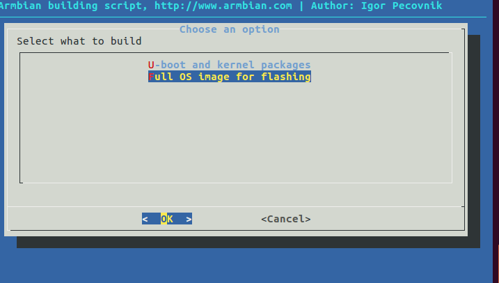
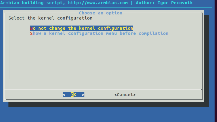
In the building options choose

armbianopipcfosWe selected the default kernel configuration

armbianopipckernel
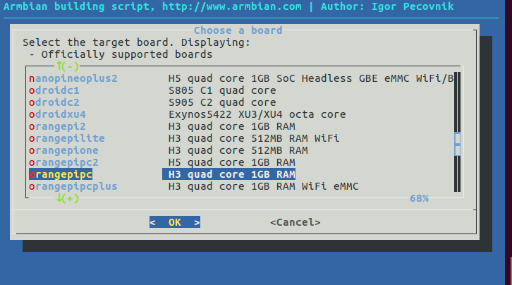
Choose an Orange PI PC board

armbianopipcboard
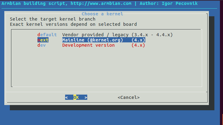
We used the mainline kernel

armbianopipcmlkernel
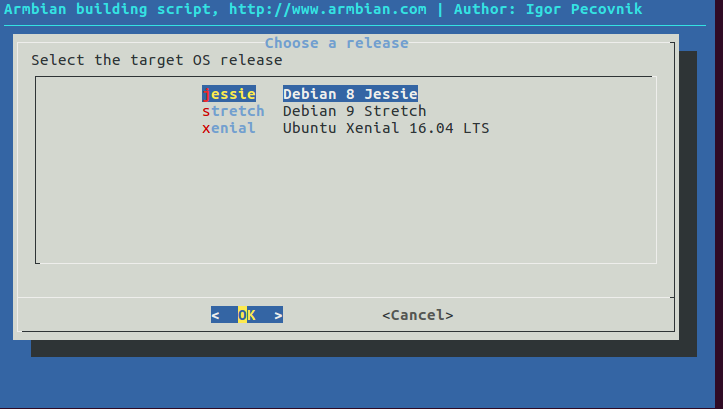
and Debian Jessie as distribution

armbianopipcjessie
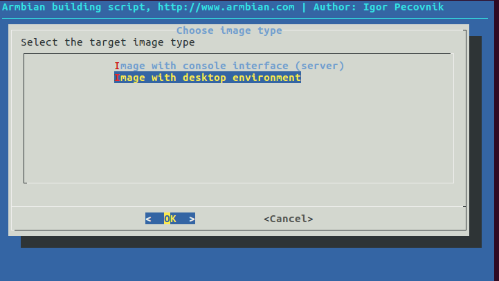
We built an image with desktop envinronment

armbianopipcjessiedeAfter this option, the script proceeds to the compilation. The generated image is Armbian_5.34_Orangepipc_Debian_jessie_next_4.13.12_desktop.img. This image can be downloaded from the link

Armbian image for Orange Pi PC

Start Armbian and create the user for the Jessie image; in this case we choose octoprint/password as user.

If necessary, reconfigure the keyboard with the command

and proceed to upgrade the system

If the system needs to be configured via a wireless connection, the connection must be active at startup. For this purpose in our case we used the Wicd daemon

Wicd Debian

Remove the network-manager package

This command uninstalls network-manager and network-manager-gnome.

Check that the wireless interface is not present in

/etc/network/interfaces

Proceed to Wicd installation

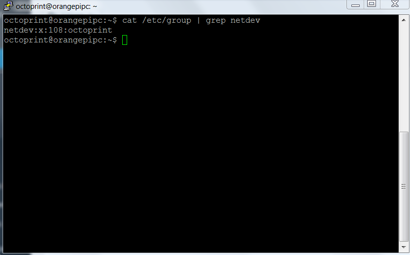
Check that the octoprint user is present in the netdev group

In our case it is already present, giving as a result

netdev-group

If not present, add it with the command

Start  wicd

Logon to the armbian graphic desktop and start the wireless configuration with the command

wicd-client

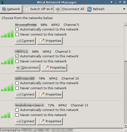
Configure and save the network connection from the graphical interface.

If you want the remote desktop follow the steps listed in the article

Remote desktop setup for Armbian on Orange PI PC

We can now install Octoprint. Follow the steps available at the link

OctoPrint installation on Linux

Install the prerequisites

Create under /opt the octoprint folder and assign the ownership  to octoprint

In a Linux shell command go to /opt/octoprint  folder and download the software

Run

Create the  .octoprint folder

Add  octoprint to the following groups  to manage the 3d printer using the USB port

Check  the correct installation by running the command
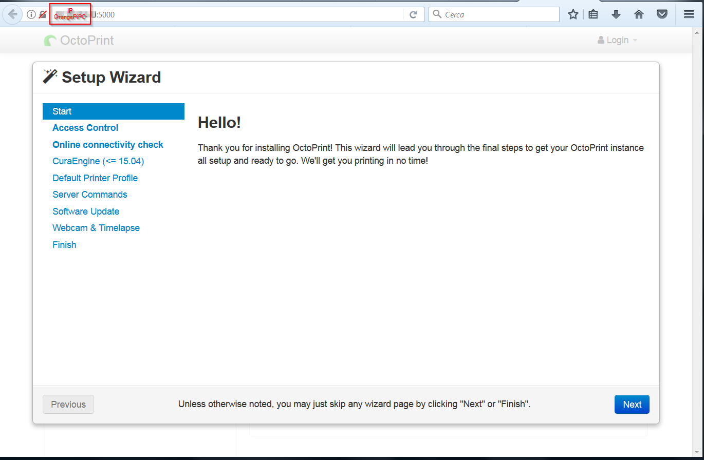
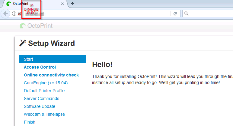
The OctoPrint server can be reached on port 5000 at the IP address of Orange PI PC

http://ipaddress:5000

octoprinttest

Install the Cura Engine at this point; place yourself in the octoprint user’s home and download the source package

Unpack the package

Go into  the unpacked folder

Run  the compilation with the command

The compiled software is located under the build folder

curaengine
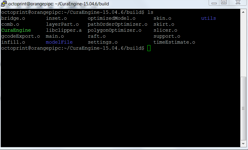
Create the /opt /octoprint/cura folder and copy the CuraEngine file to this folder

The executable is now in the /opt/octoprint/cura folder and will be used later by OctoPrint.

In the next article we’ll treat how to configure OctoPrint’s automatic startup

OctoPrint Autostart

Enigma 2 – How to read the contents of an image

In the previous article

OpenaATV Enigma2 image compilation

we built an Enigma2 image.

This shows how to view the content  of an Enigma2 image.

As an example we will always use the image for Zgemma H2H.

In a Linux environment, Debian 8 in our case, download the image to a folder, for example enigma2

enigma2 imageIn a terminal unzip it with the command

In the unpacked folder we have several files

rootfsWhat we are interested in is rootfs.bin.

The command

provides informations about the file type. In the case of rootfs.bin

ubithe command indicates that this is an image with ubi filesystem.

Now install the memory technology device utilities as the first step. In a terminal run

To view the contents run

The file  content is now visible under /mnt/ ubifs

ubimountTo unmount the filesystem run

Finally to  detach the UBI from the mtd device use the command

Below the links to find more informations about mtd and ubi filesystem

UBIFS

Linux MTD UBIFS

LEDE on Linkit 7688 Duo – Timecheck example

After the Python ad Firmata example

Firmata and Python

in this example we use the following programming model

duo-yun-bridge

We enable the board to work like Arduino Yun

Linkit 7688 Duo Arduino Yun

As specified in the Mediatek link, you must enable the bridge on the board; from a terminal in Lede run

At the reboot go to the Arduino Ide and choose File->Examples->Bridge->TimeCheck

timecheck_arduino-1-6-5We used the 1.6.5 Arduino Ide; we had issues whith the 1.8 version to build the sketch.

From the Arduino Ide, after the code upload, go to Tool->Serial Monitor to open the serial monitor

timecheckThe serial monitor window shows the current time.

After that, to run the other examples , disable the bridge setting with the commands

LEDE on Linkit 7688 Duo – Firmata and Python

After the python test in the previous article

LEDE on Linkit 7688 Duo – MPU-MCU Uart communication

here we describe how to do the same operation using the Firmata  python library

Firmata Protocol

In this case, the programming model is the following

duo-firmata-archAs first step,  described in the Mediatek article

Using Firmata with Python

we install the Firmata python library; in a linux terminal on LEDE run

In the Arduino IDE choose File->Examples->Firmata->StandardFirmata

arduinofirmataMake the following change in sketch code:

Look for the code

Firmata.begin(57600);
  while (!Serial) {

and replace it with

  Serial1.begin(57600);
  Firmata.begin(Serial1);
 
  while (!Serial1) {

Save the file and perform the compilation and upload on the Linkit 7688 Duo.

In a linux terminal  in Lede create the blink_with_firmata.py file and copy the following code inside

Save and quit.

Always in a linux terminal run now

The LED on the card should turn on and off.

Below is the link to download the two files  ready for the Link 7688 Duo

 Lede Python Firmata files

In the next article we’ll enable the board to work like Arduino Yun

LEDE on Linkit 7688 Duo – Timecheck example

LEDE on Linkit 7688 Duo – MPU-MCU Uart communication

After the building and installion of the LEDE firmware on the Linkit 7688 Duo card

Installation and configuration of Lede image on Linkit 7688 Duo

let’s test the functionality of some features on the card.

You can find the Mediatek article with the  programming model

Programming model

As a first example we treat the one on the Mediatek site as described in the title of the article

Linkit 7688 DUo MPU-MCU Uart Connection

which corresponds to the following programming model

duo-primitive-uart

As first step, Arduino IDE is configured as described in the link

Arduino IDE for Linkit 7688 Duo

the following code is uploaded on the Linkit 7688 Duo

This code manages  the LED by the MCU according to the commands that the MCU receives at the Serial1  port.

Logic is handled instedad by python code that runs on Linux; create a file for this purpose, such as blink.py in a linux command shell on the board, with the following code

Running the code

the LED on the card should turn on and off continuously.

In the next example we’ll use the Firmata python library to perform the same operation

 LEDE on Linkit 7688 Duo – Firmata and Python

Installation and configuration of Lede image on Linkit 7688 Duo

After you have attached to the board the support devices,  as specified in the previous article

Linkit 7688 Duo Connections

and built the image

Lede Image for Linkit 7688 Duo

we upload the image to the device.

Following the documentation availble at the link

Update the firmware with a USB drive

to update the firmware copy the lede-ramips-mt7688-LinkIt7688-squashfs-sysupgrade.bin file to the root directory of a FAT32 USB drive and rename it as lks7688.img.

Attach, now,  the USB drive to the HOST port of the board with an OTG cable and follow the steps

  1. Press and hold the on-board WiFi button.
  2. Press the MPU reset button once, while holding the WiFi button.
  3. Keep holding the WiFi button for about 5 seconds. Do not release until the orange LED for WiFi is off.  DO NOT press the WiFi button longer than 20s or it will upgrade the bootloader.
  4. The device will automatically reboot after firmware update is complete.

aggiornamento7688duo

You can control the operation via the USB TTL serial connected to the PC and activated on the enabled Com port  with the following settings

  • Port:  Enabled COM
  • Speed: 57600
  • Data Bits: 8
  • Stop Bits: 1
  • Parity: None
  • Flow Control: XON/XOFF

putty-configurationUse, for example, putty to connect, press Enter if the screen is not active,  and to check the steps the system is runnig when upgrading

aggiornamento

When the orange LED starts blinking at a lower frequency the card is ready to be used

On the Lede system, the wireless card is disabled by default, while Lan is operational, but only accessible via a Breakout board

Linkit Breakout

To enable the wireless card connect with putty (screen on Linux) to the previously connected USB TTL serial and  go to the /etc/config folder; edit the network file and add at the end the following section

Save and run

Edit the wireless file and add at the end the section

where Access Point and password indicate the Access Point name and password; the wireless security setting is wpa2.

Save and run

Enable the wireless, running

Access the Lede interface with the address assigned by the Access Point

lede-luciSet the password and access to the Lede management.

In this firmware, the leds on the board  are not synchronized with wireless operations, unlike from OpenWrt firmware with the Mediatek proprietary interface and drivers.

In the next article, we will give some examples of interfacing with the arduino IDE,  based on the tutorial on the Mediatek site using this custom Lede  image

 LEDE on Linkit 7688 Duo – MPU-MCU Uart communication

Installation and configuration of the Openwrt Image on Linkit 7688 and 7688 Duo

After you have attached to the board the support devices,  as specified in the previous article

Linkit 7688 Duo Connections

and built the image

OpenWrt building for Linkit 7688 and 7688 Duo

we upload the image to the device.

Following the documentation availble at the link

Update the firmware with a USB drive

to update the firmware copy the openwrt-ramips-mt7688-LinkIt7688-squashfs-sysupgrade.bin file to the root directory of a FAT32 USB drive and rename it as lks7688.img.

Attach, now,  the USB drive to the HOST port of the board with an OTG cable and follow the steps

  1. Press and hold the on-board WiFi button.
  2. Press the MPU reset button once, while holding the WiFi button
  3. Keep holding the WiFi button for about 5 seconds. Do not release until the orange LED for WiFi is off.  DO NOT press the WiFi button longer than 20s or it will upgrade the bootloader.
  4. The device will automatically reboot after firmware update is complete.

aggiornamento7688duo

You can control the operation via the USB TTL serial connected to the PC and activated on the enabled Com port  with the following settings

  • Port:  Enabled COM
  • Speed: 57600
  • Data Bits: 8
  • Stop Bits: 1
  • Parity: None
  • Flow Control: XON/XOFF

putty-configurationUse, for example, putty to connect, press Enter if the screen is not active,  and check the steps the system is runnig when upgrading

aggiornamento

When the orange LED starts blinking at a lower frequency the card is ready to be used.

Search for visible access points from your PC  and you should find an access point named LinkIT_Smart_7688_xxxxxx, where xxxxxx identifies the specific device.

Connect to this Access Point and access via browser at 192.168.100.1 or at mylinkit.local if you have satisfied the prerequisites

Getting started

collegamentolinkitEnter a password and access the next step

collegamentolinkit2Select OpenWrt for Advanced Configuration

collegamentolinkit3Set the password on OpenWrt

collegamentolinkit4entering it twice

collegamentolinkit5At this point, the system is configured as an Access Point. In our case, we wanted to set the Link 7688 Duo as a client of an Access Point with WPA2 security. To get this setting, if you have a visible network, go to the Network section of the main web console interface

accesso_linkit-smart_network1set the values for the Access Point and restart the system

accesso_linkit-smart_network2

If the Access Point is hidden, you should set the parameters directly in the configuration files in /etc /config.

Connect with putty to the previously connected USB TTL serial and  run the commands for Access Points with wpa2 security

 Save the settings

and activate the new configuration

Check the /etc/config/wireless file; you should see the addition of a new section, config wifi-iface ‘ap’,  to connect the board  to the access point

Now the card acts as a client and you can access it using the address released by the Access Point or by name as indicated by the documentation

Getting started

accesso_linkit-smartIn the next article, we’ll install and configure  the custom Lede firmware

Installation and configuration of Lede image on Linkit 7688 Duo

LEDE building for Linkit 7688 Duo

After OpenWrt image building using the Mediatek SDK

OpenWrt building for Linkit 7688 and 7688 Duo

this article describes how to generate a LEDE image for the Linkit 7688 Duo.

The steps on how to compile LEDE are available at the link

LEDE Building

Clone the code from the github in a shell command window,  always from the  Linkit folder

run

Create the src folder under Linkit and extract the compressed file

Feed for Linkit

This feed was created from Mediatek one, eliminating the binary drivers  dependency.

Copy the file to the src folder and uncompress it

Go to the Lede folder and copy the feeds.conf.default file  as feeds.conf

Run

Update the feeds  for the packages

Install the packages

Configure the kernel executing

Use the following settings

  • Target System: Mediatek Ralink MIPS
  • Subtarget: MT7688 based boards
  • Target Profile: Mediatek  LinkIt Smart 7688

menuconfigledeIn the Base system section enable mtk-linkit

mtk-linkitbasesystemSave and exit.

Run the building

where x is the number of cores to use in the building.

At the end of the process the generated image is available in the  bin/targets/ramips/mt7688/  folder as lede-ramips-mt7688-LinkIt7688-squashfs-sysupgrade.bin.

The built firmware is available here

Lede Image for Linkit 7688 Duo

WARNING: The image installation on the device is at your own risk. We accept no responsibility if the installation leads to  malfunction or block of the device.

If you upgrade the board using an usb key, you need to rename the lede-ramips-mt7688-LinkIt7688-squashfs-sysupgrade.bin file in lks7688.img.

This firmware may have malfunctions as it is not thoroughly tested and based on drivers under development.

In the next articles we’ll upload the images to the board and configure them

Installation and configuration of the Openwrt Image on Linkit 7688 and 7688 Duo