Category Archives: Development

Seeeduino XIAO – Objects Detection

After the Arduino IDE environment  configuration for the Seeeduino XIAO board in the previous article

Seeeduino XIAO – Arduino Envinronment

in this we will make a small example with this card.

In the project we’ll use the following components

  1. Ultrasonic sensor HC-SR04
  2. I2C  Oled  Display 0,96 pollici SSD1306

The first step is to install the libraries of the two components listed above on Arduino.

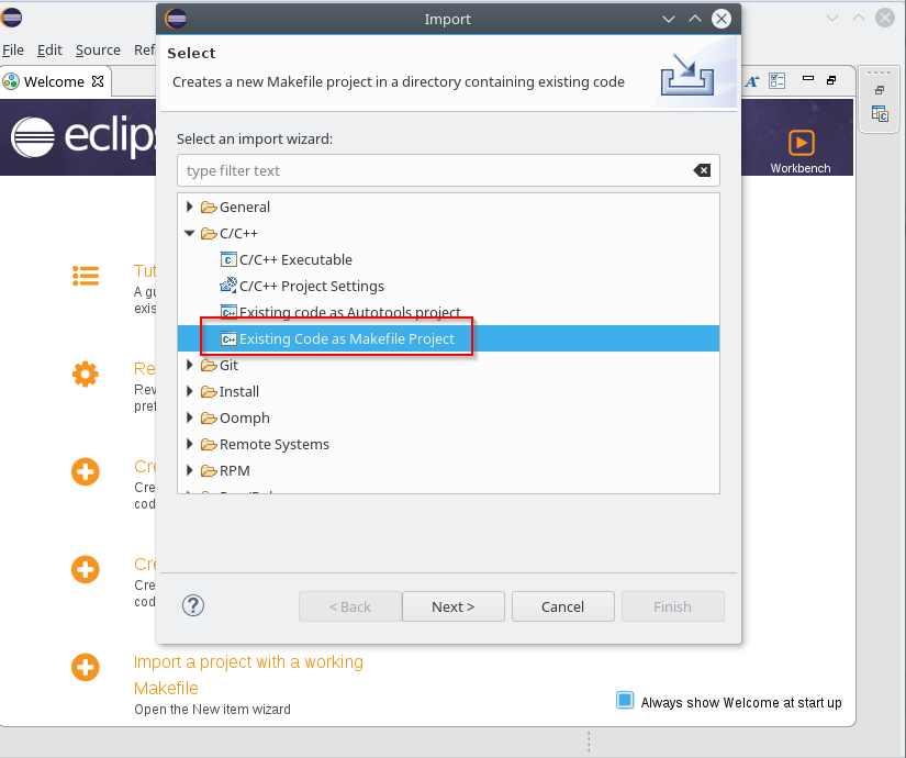
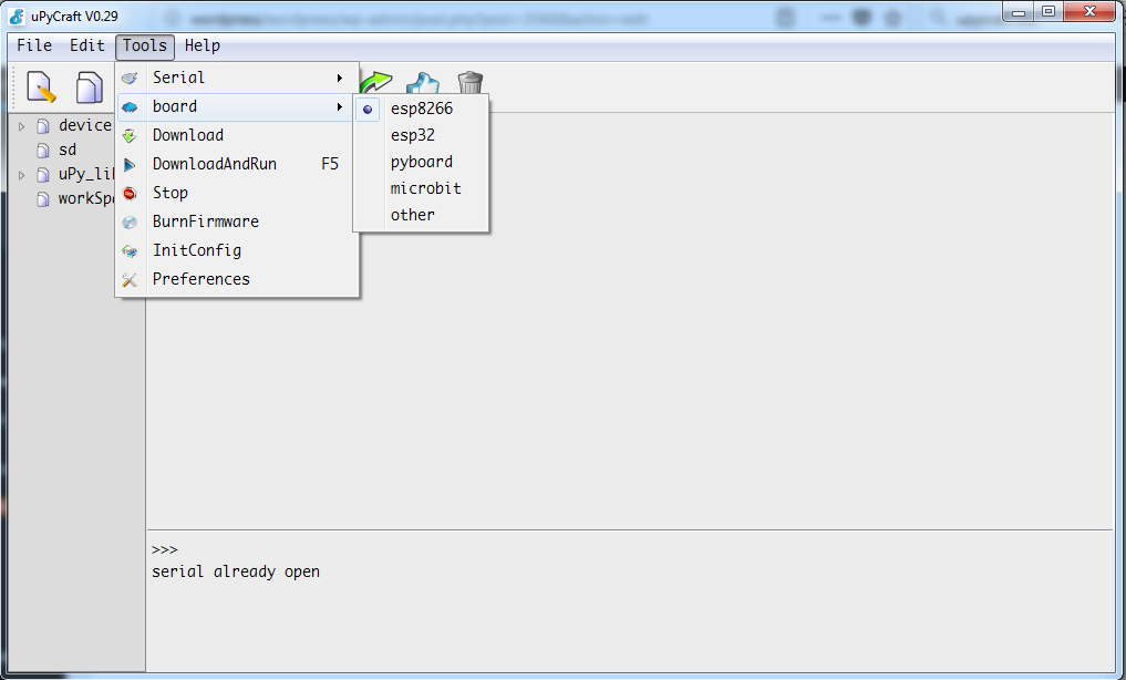
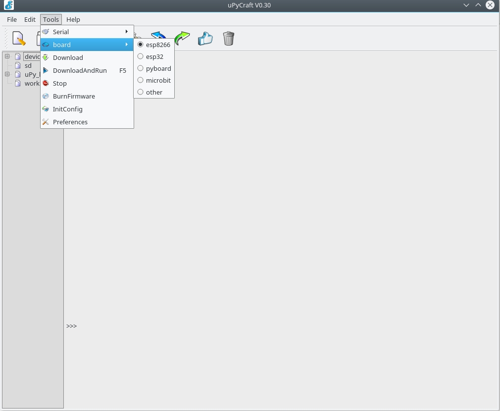
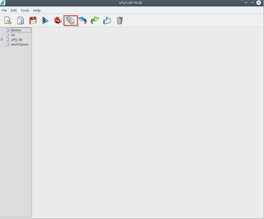
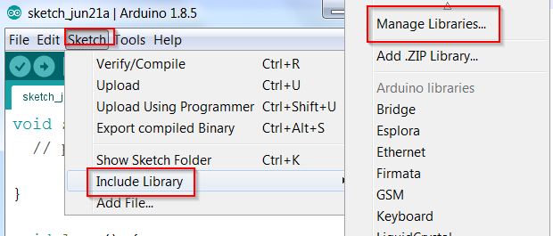
In the Arduino IDE, go to the menu  Sketch->Include Library->Manage Libraries

addlib-en
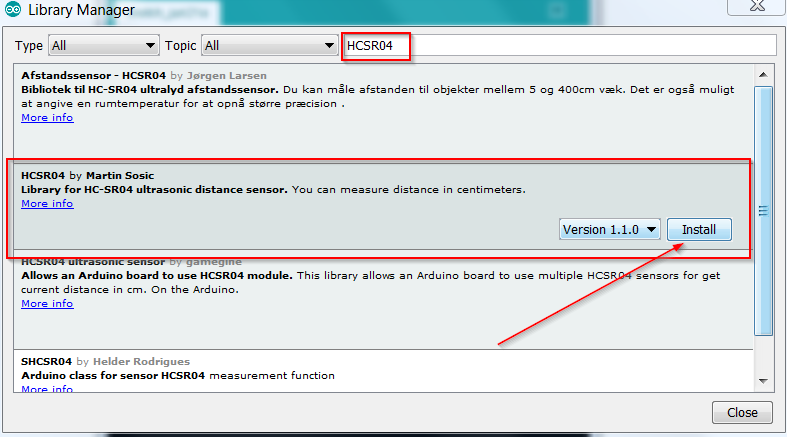
For HCSR04 we choose HCSR04 by Martin Sosic

hcsr04-enFor SSD1306 we choose ACROBOTIC SSD1306

SSD1306-en

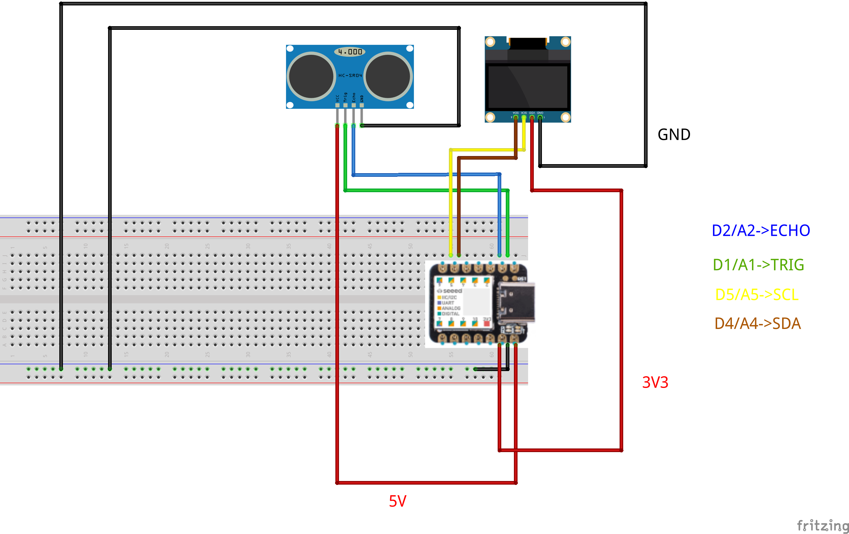
Now we have all the components for the project. We connect the components to the Seeeduino XIAO as listed in the following table

XIAO PINSSD1306 PINHCSR04 PIN
3V3VDD
GNDGNDGND
5VVCC
D2ECHO
D1TRIG
D5SCK
D4SDA

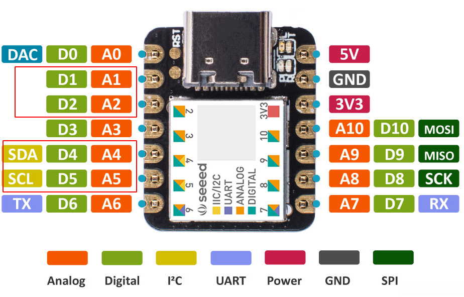
As can be seen from the table, we use the I2C and digital pins 1,2  of the XIAO

pinsexample
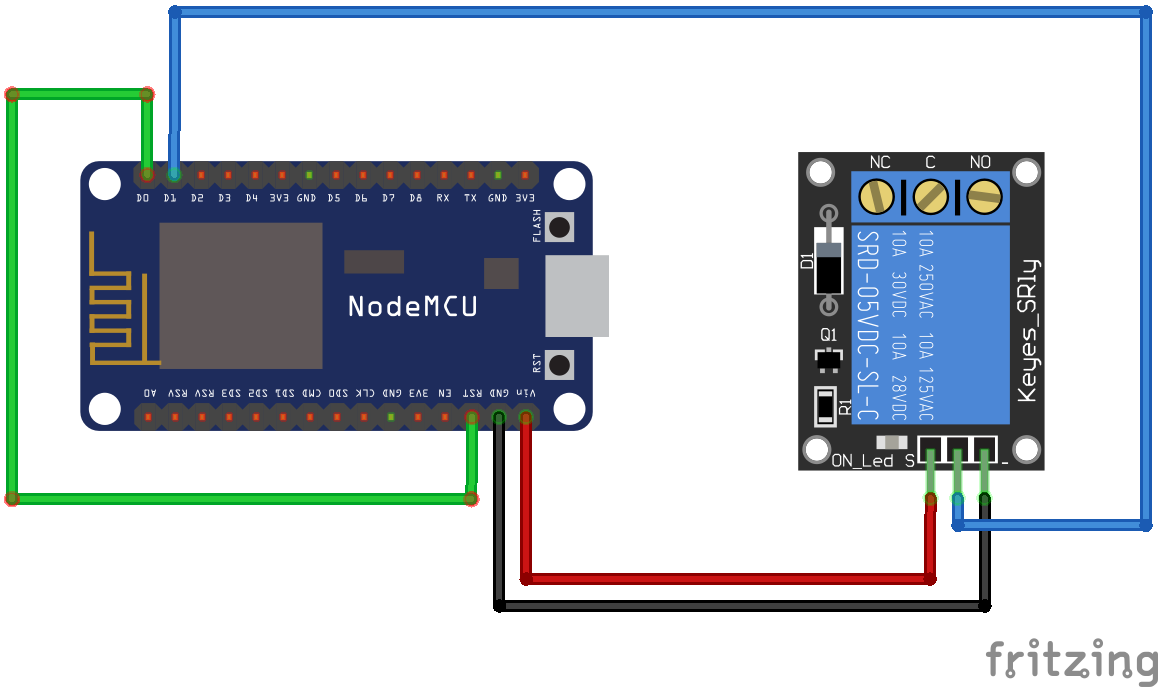
Below is the connections diagram

xiaoconnectionsThe example code is the following

If an object passes through the sensor’s field of view, the event is signaled on the OLED screen with the recorded measurement. Inside the code there are the descriptions of all the operations performed.

Here is the link to the source code file

exampleXiao.ino

ESP32 – IDF Sdk with Eclipse

After configuring the IDF development environment in the previous article

ESP32 – IDF Sdk

let’s see now how to use Eclipse as IDE for code development. Instructions are available at the link

Eclipse Setup

Download the  C/C++ Eclipse  for Linux

Eclipse Download

Unpack the file and move it to /opt/

Run ecplise

Set the workspace for eclipse

eclipse-workspaceOnce the IDE is open, select File -> Import -> C / C ++ – -> Existing Code as Makefile Project

eclipse-importPress Next; on the next screen select the folder containing the Makefile of a sample project in the “Existing Code Location” field and choose CrossGcc as “Toolchain for indexer settings” as shown below

eclipse-import2Once the project is loaded, using the mouse right button on the project name, select the properties option

eclipse-project-propertiesUnder C / C ++ Build -> Envinronment add the variable

eclipse-batchAdd the IDF_PATH variable pointing to the downloaded IDF SDK in the same section

eclipse-idf-pathEdit the PATH variable and add the path to the bin folder of the cross compiler /home/sviluppo/Esp32/espressif/esp/xtensa-esp32-elf/bin

eclipse-pathAccess “C / C ++ General” -> “Preprocessor Include Paths”; choose the Providers tab and click on “CDT Cross GCC Built-in Compiler Settings”

eclipse-cross-cdtReplace $ {COMMAND}

eclipse-cross-cdt1with xtensa-esp32-elf-gcc

eclipse-cross-cdt2Choose now, always in the providers section,  “CDT GCC Build Output Parser”

eclipse-cross-cdt3and insert at the beginning of the “Compiler command pattern” xtensa-esp32-elf-

eclipse-cross-cdt4Save the configurations.

The project settings should always be made by make menuconfig in the unix shell. Access the shell and set the LED to be switched on/off  the value 2 as GPIO; this is because in our case the card is a doit whose design is illustrated in this document


Access to Example configuration

blink-configurationand set the gpio value to 2

blink-gpioSave the configuration. Go back to Eclipse and proceed with cleaning with

eclipse-clean-blinkand subsequent compilation with Project -> Build

eclipse-build-blinkTo run firmware flash from eclipse;, select the project and with the right button choose Build Targets -> Create …

eclipse-create-targetEnter flash as value in the target name field, leaving everything else as default

eclipse-create-target-flashAt this point we proceed to upload the image by double-clicking on the new flash item within the project targets

eclipse-run-flashThe settings to run the flash must be set with make menuconfig, as seen in the previous article


MicroPython – Nodes examples with DHT11, Relay and MQTT

In a series of articles seen previously  on Mqtt, Beaglebone and ESP8266

Mqtt with Beaglebone and ESP8266 – Articles List

we have created the infrastructure for managing the ESP8266 nodes .

In this article we program the two ESP8266 nodes  using MicroPython instead of Nodemcu and Lua.

The infrastructure remains identical; on the Beaglebone there is Mqtt Mosquitto Server and Freeboard for the management of the mqtt topics, visualization and interaction.

The ESP8266 node examples with relay and DHT11 sensor use the umqtt MicroPython libraries, available on the site

umqtt simple

In the following examples, only the umqtt simple is used; in the code several delays have been inserted to allow the board to manage the messages and not run into errors; in the case the Mqtt server is not available the code restarts the board.

Below the code used for these examples.

Node with DHT11 sensor

  • boot.py: code executed at startup

  • umqtt/simple.py:  mqtt library

  • dht11.py: module for reading the temperature and humidity on the GPIO2

  • main.py: code executed after boot

  •  client_mqtt.py: Main module for node management

  • riavvia.py: service code to restart the module from uPyCraft


Node with relay

  • boot.py: code executed at startup

  • umqtt/simple.py: mqtt library

    • main.py: code executed after boot

    •  client_mqtt.py: Main module for node management

  • riavvia.py: service code to restart the module from uPyCraft

Below is the filesystem on ESP8266 for the relays sample

ESPFilesystemBy accessing Freeboard we have the same informations obtained with Nodemcu and LUA on ESP8266 nodes

FreeboardMicroPythonBelow are the screens with MQTT Dashboard installed on an Android smartphone, with the possibility to check the status of the relay, read the sensor parameters, restart and sleep the two nodes

MqttPublish

MqttSubscribe

Here are the links to download the two examples

DHT11 sensor sample

Relay sample

In the next article we will compile the MicroPython firmware for ESP8266

MicroPython – MicroPython compiling for ESP8266


MicroPython – MicroPython program structure

After reviewing various development tools for MicroPython in previous articles

MicroPython – Development tools Ampy – Eric

MicroPython IDE uPyCraft

in this article we briefly describe the main features of MicroPython. In particular, we examine the documentation relating to the ESP8266, but the concepts can also be extended to the other boards.

The documentation on the ESP8266 soc and MicroPython  is available at the link

ESP8266 MicroPython Documentation

At the link we can find all the informations necessary to implement the code on the card and the features of MicroPython as well as the differences compared to Python.

Here are the main points for coding in MicroPython:

  • MicroPython has a REPL (Read Evaluate Print Loop) console through the serial port to which the device is connected on which we can give the various MicroPython commands interactively.
  • The REPL console can also be accessed via connection to the IP address of the device by enabling the WEBREPL (Web Browser Interactive prompt) console

WebREPL Documentation

importing the webrepl package, enabling it and starting it at each device restart. To access the configured device, we can use the link

WEBREPL Access

or locally cloning it  from github

  • At the start of the device the system runs boot.py and after main.py.
  • The MicroPython libraries are available on the github at the link

MicroPython libraries

  • Additional packages

The additional modules can be downloaded from the link of the libraries presented above or downloaded with the upip utility (Package Manager) from the REPL console if available in the Python Package Index (PyPI) repository

PYPI

as described below

upip

Below is a simple example that connects to the router and allows us to access the MicroPython console with the browser and WEBREPL.

  • boot.py code

At the first access it is required to enable webrepl to be executed in the REPL console with the command

we can activate the service and the access password.

The procedure generates the webrepl_cfg.py file on the device.

After setting up and restarting, we access the web console by opening the locally cloned webrepl.html file with a browser

WebreplPressing connect and after entering the password ,set in the initial setup, we access the console

WebreplConnectedNow we install from the WEBREPL console, for example, the stat module using upip

To paste commands  execute Ctrl+A e Ctrl+V

WebreplupipIn this case the package was taken from the PYPI repository, unpacked and installed on the device.

We have noticed that some modules, although available on the repository, give an error during installation with upip; these modules are installed directly without using the upip utility,but by downloading the library from the site listed above and transferring the code to the device.

Here is the link of the code shown above

Webreplsample

Another option available is to build  the firmware with the required modules.

In the next article we will examine examples similar to what was done with LUA on ESP8266 in previous articles

MicroPython – Nodes examples with DHT11, Relay and MQTT


Micropython – Development tools Ampy – Eric

After the  uPyCraft  intallation in the previous article

MicroPython – IDE MicroPython uPyCraft

let’s now look at other tools available for the development in MicroPython for various platforms.

This article shows the operations to be performed on Windows and Linux.

First Python package to install is Ampy (Adafruit MicroPython Tool)

ampy

The tool is available in the python repositories, so it can be installed using the  pip tool.

In Windos run in a dos command prompt

Similarly in Linux run in a shell

The available commands are listed running

ampyAmpy allows the transfer, creation, viewing, and execution of files on the device.

As for the IDE you can install Eric, generic Python IDE

Eric

Eric does not allow communication from the IDE with the device as seen with uPyCraft; this task is delegated to Ampy. For the installation proceed as follows:

  • For Linux Debian 9 just run

The tool is available among the development tools; at the first execution it requires default settings

ericSettingsWe define the workspace location

ericWorkspaceand we have the access to the IDE

eric

  • For Windows download the zip

Eric

Unzip the zip into a folder from which we run it; install the prerequisites

Perform the eric installation at this point by double clicking on install.py

ericInstallWindowsThe program checks the prerequisites and completes the installation

ericWindowsProcedure

Clicking twice on eric6.py or running eric6 from a dos command prompt we run the program in the same way as seen for Linux Debian

ericWindows

In the next article we will briefly examine how a MicroPython program is structured

MicroPython – MicroPython program structure


Micropython – MicroPython IDE uPyCraft

After installing the firmware on the Nodemcu esp8266 DevKit board

MicroPython Firmware

let us now examine a development tool can be suitable for the development of Python code.

A tool that allows both to write code and upload it to the device is uPyCraft

uPyCraft

The tool currently works for Windows and from version 0.30 is also available for Linux; the source code is available at the link

uPyCraft Source

Here are the steps for Windows and Linux.

  • Windows

Once downloaded the package we must  run it as an administrator; the installation of the Monaco font is required

monaco-font

After the font installation,  we have the access to the IDE

upycraft-v0-29We set the Location in Tools->Preferences->Language Location

upycraftlocation

and the serial port paramenters in Tools->Preferences->Serial

upycraftserialsettingsWe plug the device into an USB port and set the serial port on uPyCraft

upycraftserialWe choose the device type; in this case it is ESP8266

upycraftdeviceBy clicking on the connection icon we access to the device and view the files on it

upycraftconnectionThe firmware installation expands on the device only the Python file boot.py

upycraftfilesystemThe tool allows to download examples of MicroPython code for the board, blink.py for example

examplesClicking the “Download and Run” button we load the code onto the device and run it

blinkIn this example the led of the Nodemcu DevKit blinks.

  • Linux

The tool is similar in the Linux version; once downloaded the package to which we have to assign  the execution right we run it. We must assign to the user the access to the serial port with the command, already seen above

In our case, on Debian 9, we have the following screens similar to what we saw on Windows.

In the uPyCraft IDE

upycraft-v0-30linuxWe set the Location in Tools->Preferences->Language Location

upycraftlocationlinux

and the serial port paramenters in Tools->Preferences->Serial

upycraftserialsettingslinuxWe plug the device into an USB port and set the serial port on uPyCraft

upycraftseriallinuxWe choose the device type; in this case it is ESP8266

upycraftdevicelinuxBy clicking on the connection icon we access to the device and view the files on it

upycraftconnectionlinuxThe firmware installation expands on the device only the Python file boot.py

upycraftfilesystemlinuxThe tool allows to download examples of MicroPython code for the board, blink.py for example

exampleslinuxClicking the “Download and Run” button we load the code onto the device and run it

blinklinuxAs in Windows the led of the Nodemcu DevKit blinks..

In version 0.30 for Windows we noticed some bugs, so for this operating system we continue to use the uPyCraft  version 0.29.

Further informations about uPyCraft can be found at the following site

uPyCraft Documentation

In the next article we will discuss another Python development tool

MicroPython – Development tools Ampy – Eric

LEDE on Linkit 7688 Duo – MPU-MCU Uart communication

After the building and installion of the LEDE firmware on the Linkit 7688 Duo card

Installation and configuration of Lede image on Linkit 7688 Duo

let’s test the functionality of some features on the card.

You can find the Mediatek article with the  programming model

Programming model

As a first example we treat the one on the Mediatek site as described in the title of the article

Linkit 7688 DUo MPU-MCU Uart Connection

which corresponds to the following programming model

duo-primitive-uart

As first step, Arduino IDE is configured as described in the link

Arduino IDE for Linkit 7688 Duo

the following code is uploaded on the Linkit 7688 Duo

This code manages  the LED by the MCU according to the commands that the MCU receives at the Serial1  port.

Logic is handled instedad by python code that runs on Linux; create a file for this purpose, such as blink.py in a linux command shell on the board, with the following code

Running the code

the LED on the card should turn on and off continuously.

In the next example we’ll use the Firmata python library to perform the same operation

 LEDE on Linkit 7688 Duo – Firmata and Python

Libreelec8 addon building for Orange PI PC

In the article about the Libreelec8 build for Orange PI PC

Libreelec8 in OrangePI PC

we created the environment and compiled the Libreelec8 image for our development board. We integrate what it has been said in the previous article showing how to build  the Libreelec 8 addons for our Orange PI PC board.

Now we proceed to build some addons. The packages that you can build are available in the kodi-binary-addons folder as shown below

libreelec8 addonsand in the packages/addons folder

addons packages

We build the  pvr.iptvsimple addon running the following command from the /home/sviluppo/orangepi/libreelec/libreelec-8.0 folder

addon command

We build the proftpd addon, among those avaliable in the packages/addons  folder

The compiled addons are available in the following folder

addons

Here are the links to download some compiled addons

PVR addons

Service Addons

Libreelec8 in OrangePI PC

This article describes the steps that I ran to prepare a first version of Libreelec 8 in Orange PI PC cards and other H3 socs.

Starting from the Debian development envinronment, with its installed packages, already used for the compilation of OpenELEC 7

 Openelec compilation for Orange PI PC

we proceed to build an Libreelec 8 image.

We started as basis from the work done for Openelec 7 and Libreelec 7 available on the two github repositories

H3 Openelec 7 Github

H3 Libreelec 7 Github

Log in a unix command shell as user sviluppo; create a folder, libreelec , under orangepi folder and move into it

Clone the Libreelec8 github

The patches have been created for a specific version of the commit, so we align our github clone to that version

Download from the following link the patches, the H3 project and other stuff

H3 Libreelec 8

Unzip this file in /home/sviluppo/orangepi/libreelec

Run the following steps

1)Copy  to /home/sviluppo/orangepi/libreelec/libreelec-8.0/projects the folder

H3

2) Copy to /home/sviluppo/orangepi/libreelec/libreelec-8.0/packages/multimedia  the folders

cedarx
libmpeg2

3) Copy to /home/sviluppo/orangepi/libreelec/libreelec-8.0/packages/tools the folder

sunxi-tools

4) Copy to /home/sviluppo/orangepi/libreelec/libreelec-8.0/packages/sysutils  the folder

  sunxi-sys-utils

5) Copy to /home/sviluppo/orangepi/libreelec/libreelec-8.0/packages/graphics  the folder

sunxi-mali

6) Copy to /home/sviluppo/orangepi/libreelec/libreelec-8.0/packages/linux-drivers  the folder

mt7601u

7)  The following patches are available in /home/sviluppo/orangepi/libreelec/H3LE8/patches folder

linux.patch

image.patch

mkimage.patch

kodi.patch

libcec.patch

u-boot.patch

u-boot-release.patch

u-boot-update.patch

Patch the code from the /home/sviluppo/orangepi/libreelec folder running the following commands

Proceed to the image build for Orange PI PC from the folder /home/sviluppo/orangepi/libreelec/libreelec-8.0  running

At the end of the compilation in the /home/sviluppo/orangepi/libreelec/libreelec-8.0/target folder we find the files to install or update Libreelec 8

 At the link

Openelec 7 H3 FAQ

we find the boards we can build changing the SYSTEM parameter in the building command

SYSTEM=opi2
SYSTEM=opione
SYSTEM=opipc
SYSTEM=opiplus
SYSTEM=opilite
SYSTEM=opipcplus
SYSTEM=opiplus2e
SYSTEM=bpim2p
SYSTEM=bx2

This image is a first attempt to build Libreelec 8 for  H3  socs. The image was installed on Orange PI PC and the system worked well, but still bugs and malfunctions may occur.

Here is the built Libreelec 8 image for Orange PI PC

Orange PI PC Libreelec 8 Image

We tested this image on an Orange PI PC board.

Here are other images we did’t test on the devices

Orange Pi2 Libreelec 8 Image

Orange Pi Lite Libreelec 8 Image

Orange Pi One Libreelec 8 Image

Orange Pi PC Plus Libreelec 8 Image

Orange Pi Plus Libreelec 8 Image

Orange Pi Plus 2e Libreelec 8 Image

WARNING: The image installation on the device is at your own risk. We accept no responsibility if the installation leads to  malfunction or block of the device.

The following article shows how to build the addons

Libreelec 8 addon building for Orange PI PC

MQTT with BeagleBone and ESP8266 – MQTT on ESP8266 with Relay

After the article about the connection with the temperature and humidity sensor

MQTT with BeagleBone and ESP8266 – MQTT on ESP8266 with temperature sensor

in this article we set the esp8266 to run a relay. Here is how we connect the relay to the ESP module

nodemcu relay

In this example too we will consider the option of putting the nodemcu in sleep. To have the node back form the sleep the system has to reboot and  it is necessary to connect the PIN D0 (GPIO16) to RST PIN as specified in the nodemcu documentation

Nodemcu sleep

Let us take a look at the lua code; It consists of init.lua and relay.lua files.

We analyze now the main points of each file

  • init.lua

In the file we set the the parameters to access the wifi network, the address and port of the MQTT broker  and the file to be run on the ESP after wifi connection to the access point is estabilished. If the ESP doesn’t acquire the network address the system is restarted.

  • relay.lua

The relay.lua file manages the relay, the subscription on MQTT broker with submission of the data. Global parameters have been set to manage the topic, the waiting time in tmr.alarm. There are in particular the following topics

  • /home/relay1/status : Status topic. The status is sent at the start and at  request from the command topic /home/relay1/command.
  • /home/relay1/monitor: Status of the esp sent periodically to this topic.
  • /home/relay1/command: Other clients can send commands to the esp:
    • Restart: Restarts the esp.
    • Sleep n: Put to sleep for n seconds the esp.
    • ON: Turn on the  relay.
    • OFF: Turn off the  relay.
    • Status: Request of tthe relay status (ON or OFF).

There are various service functions to manage all. The comments in the code describe each feature.

In the next article we will set up the webserver on Beaglebone and the websocket configuration for Mosquitto always on the Beaglebone

MQTT with BeagleBone and ESP8266 – WebServer and MQTT WebSocket