Tag Archives: nodemcu

ESP32 – Nodemcu firmware compiling

After  the compilation of the MicroPython firmware for ESP32

ESP32 – MicroPython compiling for ESP32

this article shows how to generate the Nodemcu firmware for the ESP32 MCU.

The firmware is not yet complete as the one existing for ESP8266.

The instructions can be found on the github at the link

https://github.com/nodemcu/nodemcu-firmware/tree/dev-esp32

The compilation documentation is available at the link

https://nodemcu.readthedocs.io/en/dev-esp32/en/build/

The operating system used is Debian 9 previously encountered for the esptool and Adafruit-ampy utilities

MicroPython – Python on embedded devices

Log on  with the operating system user on Debian 9, sviluppo in our case; under the home folder  create the Esp32 folder and inside this folder the  nodemcu  folder

Clone the repository

To update the cloned repository follow the description on the compilation link, i.e.

Go into  nodemcu-firmware-esp32 folder and run

nodemcu-settings
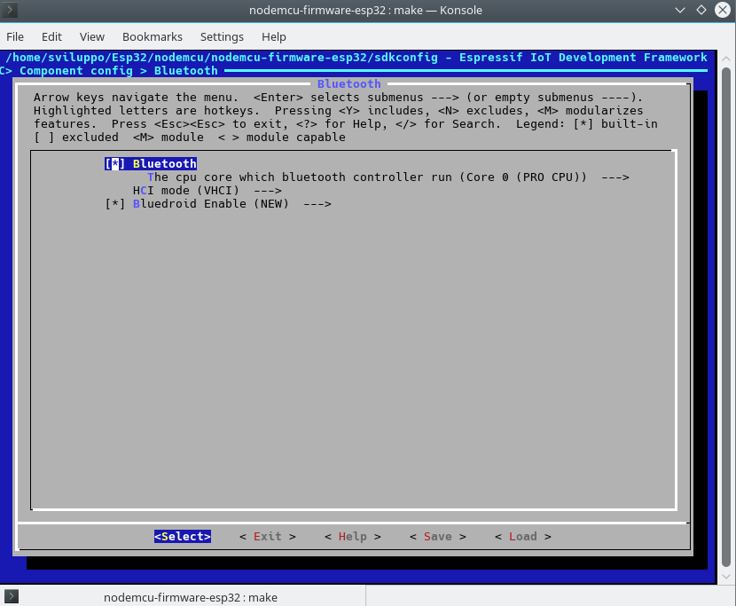
Enable the bluetooth  in Component config–>Bluetooth

nodemcu-bluetooth
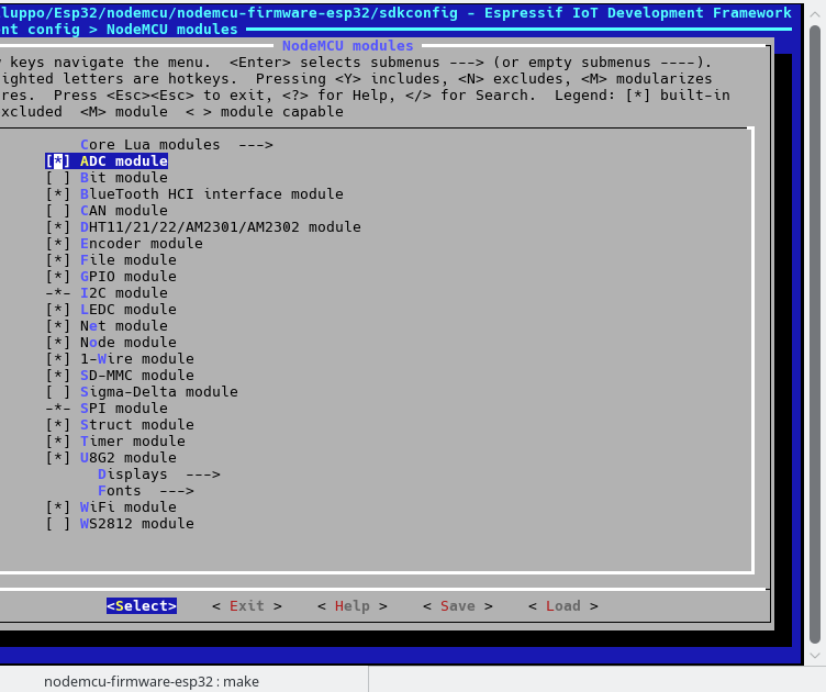
Enable various modules in Component config–>Nodemcu modules

nodemcu-modules
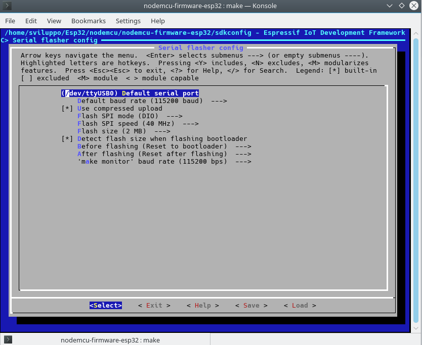
In the flash settings we set the default values for our ESP32,  Serial flasher config->

nodemcu-flashSave the configuration and exit. To build the firmware run

At the end of the compilation the command to upload the firmware  is shown; the same operation is executed  by simply running

For informations about the partitions of the various ESP32 versions, refer to the documentation

http://api-guides/partition-tables.html

In the next article we’ll  show how to make an application using the Espressif SDK

ESP32 – IDF Sdk

MQTT with BeagleBone and ESP8266 – MQTT on ESP8266 with Relay

After the article about the connection with the temperature and humidity sensor

MQTT with BeagleBone and ESP8266 – MQTT on ESP8266 with temperature sensor

in this article we set the esp8266 to run a relay. Here is how we connect the relay to the ESP module

nodemcu relay

In this example too we will consider the option of putting the nodemcu in sleep. To have the node back form the sleep the system has to reboot and  it is necessary to connect the PIN D0 (GPIO16) to RST PIN as specified in the nodemcu documentation

Nodemcu sleep

Let us take a look at the lua code; It consists of init.lua and relay.lua files.

We analyze now the main points of each file

  • init.lua

In the file we set the the parameters to access the wifi network, the address and port of the MQTT broker  and the file to be run on the ESP after wifi connection to the access point is estabilished. If the ESP doesn’t acquire the network address the system is restarted.

  • relay.lua

The relay.lua file manages the relay, the subscription on MQTT broker with submission of the data. Global parameters have been set to manage the topic, the waiting time in tmr.alarm. There are in particular the following topics

  • /home/relay1/status : Status topic. The status is sent at the start and at  request from the command topic /home/relay1/command.
  • /home/relay1/monitor: Status of the esp sent periodically to this topic.
  • /home/relay1/command: Other clients can send commands to the esp:
    • Restart: Restarts the esp.
    • Sleep n: Put to sleep for n seconds the esp.
    • ON: Turn on the  relay.
    • OFF: Turn off the  relay.
    • Status: Request of tthe relay status (ON or OFF).

There are various service functions to manage all. The comments in the code describe each feature.

In the next article we will set up the webserver on Beaglebone and the websocket configuration for Mosquitto always on the Beaglebone

MQTT with BeagleBone and ESP8266 – WebServer and MQTT WebSocket

MQTT with BeagleBone and ESP8266 – MQTT on ESP8266 with temperature sensor

After loading the firmware into the device esp8266

MQTT with BeagleBone and ESP8266-MQTT ESP8266

we now connect this module with a DHT11 temperature and humidity sensor. Here is how we connect the sensor to the ESP module

nodemcu dht11

In this example we will consider the option of putting the nodemcu in sleep. To have the node back form the sleep  the system has to reboot and  it is necessary to connect the PIN D0 (GPIO16) to RST PIN as specified in the nodemcu documentation

Nodemcu sleep

Let us take a look at the lua code; It consists of init.lua and tempumid.lua files.

We analyze now the main points of each file

  • init.lua

In the file we set the the parameters to access the wifi network, the address and port of the MQTT broker  and the file to be run on the ESP after wifi connection to the access point is estabilished. If the ESP does’t acquire the netowrk address the system is restarted.

  • tempumid.lua

The temumid.lua file manages the measurement of temperature and humidity, the subscription on MQTT broker with submission of the data. Global parameters have been set to manage the topic, the waiting time in tmr.alarm. There are in particular the following topics

  • /home/room1/temperature: measured temperature topic.
  • /home/room1/humidity: measured humidity topic.
  • /home/room1/status : Status topic. The status is sent at the start and at  request from the command topic /home/room1/command.
  • /home/room1/monitor: Status of the esp sent periodically to this topic.
  • /home/room1/command: Other clients can send commands to the esp:
    • Restart: Restarts the esp.
    • Sleep n: Put to sleep for n seconds the esp.

There are various service functions to manage all. The comments in the code describe each feature.

In the next article we will set up the esp with the relay

MQTT with BeagleBone and ESP8266 – MQTT on ESP8266 with Relay


Mqtt with Beaglebone and ESP8266-MQTT ESP8266

After installing the MQTT server on BeagleBone

Mqtt with Beaglebone and ESP8266-Mosquitto installation on Beaglebone

let us set the MQTT nodes on ESP8266.

As first operation we must generate the nodemcu firmware, as described in the previous article

Nodemcu compilation on Linux

with at least the following parameters activated in user_module.h file

  • DHT
  • file
  • GPIO
  • MQTT
  • net
  • node
  • timer
  • UART
  • WiFi

These settings are the default in the user_module.h file.

At present the latest version 2.0 of nomemcu firmware was released. Here are the compiled files for this version of the firmware

Nodemcu2.0.0 firmware

As already described in previous articles and from the nodecmu link on flashing

Flashing the firmware

 we have to set the correct parameters for  the  esp8266 model.

In our case, with 4MB flash, we used the parameters shown in the image to load the firmware on the device with nodemcu-flasher tool. You can also use other tools for loading the firmware. In our case, the settings used are as follows

nodemcu flasherIn the next article we’ll treat the ESP8266 node that detects temperature and humidity

MQTT with BeagleBone and ESP8266 – MQTT on ESP8266 with temperature sensor

MQTT with BeagleBone and ESP8266 – Mosquitto installation on Beaglebone

After summarizing the architecture that we are implementing in the previous article

 Mqtt with Beaglebone and ESP8266-Architecture

We proceed now with the installation of the MQTT broker on Beaglebone Black with the following version of Debian

The image used is the following

Beaglebone Black Image

We proceed to the configuration as described in the article

Debian sd card setup for Beaglebone Black

Proceed to extend the space on the SD card  with the application gparted in a linux host or using the grow_partition.sh tool on BeagleBone in the /opt/scripts/tools folder

Performing the upgrade with this image we have  had space issue with 4Gb partition.

The message broker we’ll use is  mosquitto

Mosquitto

The version of Mosquitto with Debian Jessie  doesn’t not have the Wesockets services, which we’ll use for the Dashboard. For this reason, we have to install a more recent version of Mosquitto  (or recompile it from source).

Log on as root in a command shell on BeagleBone and add the Debian testing repository

Run the following

After the installation comment  the reference of the debian testing repository  in /etc/apt/sources.list

and run

We test at this point if the server is installed correctly by running in a shell the subscription to a topic

In another command shell run the publishing on topic “topic / test”

The first shell has to show the message “Prova”

mqtt Test

With MQTT protocol we can define different QOS, as described in the  Mosquitto FAQ

QOS Mosquitto

With QoS = 0 the message is sent only once and is not required confirmation of receipt by the subscribers; the MQTT implementation in these articles is without protection with name/password or ssl channel encryption and with QOS=0.

In the next article we’ll proceed to the preparation of ESP9266 module with the Mqtt lua library inside the nodemcu firmware

MQTT with BeagleBone and ESP8266-MQTT ESP8266

Mqtt with Beaglebone and Esp8266-Architecture

In this series of articles we treat a MQTT message broker installed on  BeagleBone Black; this componet   allows  to manage various esp8266 devices, to which we connect various probes such as temperaure sensors, relays.

All this is handled with the help of apps on Android and a Dashboard installed on Apache on BeagleBone.

We start from the message MQTT broker (Message Queue Telemetry Transport); here there is the description of the protocol

MQTT

In particular in the FAQ section there are the first indications on the protocol and its use

MQTT Faq

The system is formed by three components:

  • MQTT Broker: relays the messages published to all subscribers.
  • Publisher: Publish messages in the registered topics on MQTT Broker.
  • Subscriber: Receives messages for its registered topics from MQTT Broker.

The following shows the topology for two topics used in our example

archThe system is composed of a MQTT  broker on BeagleBone. In this MQTT broker server you can define topics; different devices can be registered to these topics. For each topic the action can be subscription and publishing. By subscribing you receive all messages of topics, while with the publishing we can perform actions on the topic (for example, turn on a relay, restart a device, send sensor measurement,etc.). In the example we treat there will be, for example, a queue for the temperature monitor, hooked to esp8266 temperature reading device, another for the management of a relay, always run with esp8266. The MQTT broker relays the received messages among all  subscribers/ publishers for each topic.

We can subcribe/publish to the topics on the MQTT broker using  Android apps; the apps can receive messages and send commands to the esp8266 end device (Turn onRelay, Restart sensor, etc.).

With the javascript framework Freeboard

Freeboard

installed on the Beablebone Apache web server we can monitor in real time the end devices.

For more informations on MQTT system, consult the web site listed above.

In the next article we’ll start by installing the MQTT broker on BeagleBone Black

MQTT with BeagleBone and ESP8266 – Mosquitto installation on Beaglebone

Nodemcu Enduser_setup module lua sample(part2)

After the firmware build and its upload to the nodemcu dev kit, we connected a switch to pin D5, as shown in the previous article

Nodemcu Enduser_setup module lua sample(part1)

We finally can upload some sample code in which we use the enduser_setup module

Open ESPlorer and load the following sample code

  • webserver.lua

  • riasserawifi.lua

  • init.lua

 It is possible to download the above samples at the following link

 Sample code

Here is the documentation about the enduser_setup module

enduser_setup module documentation

The example consists of three files:

  1. init.lua:  It is executed at the startup of the esp8266.
  2. riazzerawifi.lua: It starts the portal to connect and save the configuration to your Access Point.
  3. webserver.lua:  It starts the webserver sample on the nodemcu.

As you can see from the code in init.lua, when the pin D5 is in the state HIGH, we start the portal using enduser_setup module. In the case in which the pin D5 is in the state LOW the  esp8266 acquires the IP from an Access Point defined previously after which the test webserver starts.

To save the access point confguration to which we want to connect we place the switch in order to have the HIGH input on pin D5 and reboot the card.

From a PC we can observe the presence of another access point, defined in the file riazzerawifi.lua

composed by Mynode string + ChipID module

nodemcu portal wifiWe can connect to this access point and  via browser we  access to the portal at the ip address 192.168.4.1

Login portal wifi nodemcuSelect or enter the SSID of an access point providing the correct   password. After the connection reposition the switch to have  the LOW state  for pin D5 and reboot the nodemcu dev kit.

Now the system will automatically connect to the SSID defined previously and starts the example of the web server.

Please refer to the Lua documentation nodemcu for further study and usable modules

LUA Nodemcu Documentation

Nodemcu Enduser_setup module lua sample(part1)

In the previous article we showed a sample LUA code for ESP8266

Lua sample code for esp8266

Let us now see an example in which we’ll use the enduser_setup Lua module.

As a first step we compile the nodemcu firmware by including the enduser_setup module. We have to apply the same steps discussed in the build process article

Nodemcu firmware build

editing the app/include/user_modules.h file and uncommenting the line

After the building and firmware upload to the device, we use a switch connected to nodemcu dev kit as shown in the picture

reset access point nodemcu

The pin D5 can be connected to a low or high input voltage. Based on the input voltage we can change the behavior of the system.

Note: The Pin D5 in this specific example has been used as Input Pin; in the case of use as Output Pin, you must insert a resistor to limit the output current, as specified in the link

GPIO Pin Allocations

In the next article we’lll upload a LUA sample code with enduser_setup module enabled and we’ll utilize it to manage the wifi connections

Nodemcu Enduser_setup module lua sample(part2)

Lua sample code for esp8266

As mentioned in the previous article

how to upload nodemcu firmware with esptool

we are now ready to upload some example code on ESP8266 system.

We follow the LUA Nodemcu documentation

Nodemcu LUA Documentation

and upload a simple http server on the system.

Using ESPlorer  we  upload the following code, a modified version of the code available on the github. Modify the fields “SSID” and “password” with the the values of your Wi-fi Router.

webserver pin

Save the file as ipstatico.lua. With ESPlorer upload the file to nodemcu devkit with “Save to ESP” button .
Create a second file named init.lua

Save this file on the device.

Reboot the device with the reset command on ESPlorer tool and from the ESPlorer  command bar execute

ESPlorerThis command  provides us the ip acquired by the device. We are able now to access with a browser to the assigned ip address, discovered above, and interact with a small interface that allows us to activate or not the PIN1 output

webserverlua

With this method, however, we need to know the Access Point to which you must connect. To overcome this limitation, we can use the enduser_sertup module

Enduser_setup module

With this module we start the ESP8266 device as an access point with a portal on which we can enter the credentials of the access point which we  want to connect.

In the next article we’ll build the nodemcu firmware by adding the  enduser setup module, not available in the standard firmware, and we will do the same example using this  module

Enduser_setup module sample

How to upload nodemcu firmware with esptool

In the article about the Nodemcu firmware building

Nodemcu firmware building

we created in the bin folder the  0x0000.bin and 0x100000.bin files and copied the  blank.bin and esp_init_data_default.bin files from the Espressif SDK.

According to the esptool tool documentation

esptool

the generic  command to load the firmware is the following

In our case, as we have a development kit with 4M of flash and an 9600 USB bps we have to specify the following parameters

  • mode=dio
  • size=32m

 Always according to the esptool documention, not generating the firmware with docker, we merged the two files, 0x0000.bin and 0x100000.bin,  into the nodemcu_float.bin file

 For our development kit we need to use the other two files

  • esp_init_data_default.bin: default init data.
  • blank.bin: to reset the configuration.

according to the mapping available at the following link

ESP8266 Guide

In our case we have to use (4M flash)

  • 0x3FC000 address for  esp_init_data_default.bin.
  • 0x3FE000 address for blank.bin

In the shell command window move into nodemcu-firmware and set the PATH variable

Then execute the following commands, with /dev/ttyUSB0 as COM port of the nodemcu dev kit

  • Flash erase

  • Firmware upload

In the next article we’ll upload our custom LUA code on the nodemcu dev kit.

Lua sample code