Tag Archives: development board

Installation and configuration of the Openwrt Image on Linkit 7688 and 7688 Duo

After you have attached to the board the support devices,  as specified in the previous article
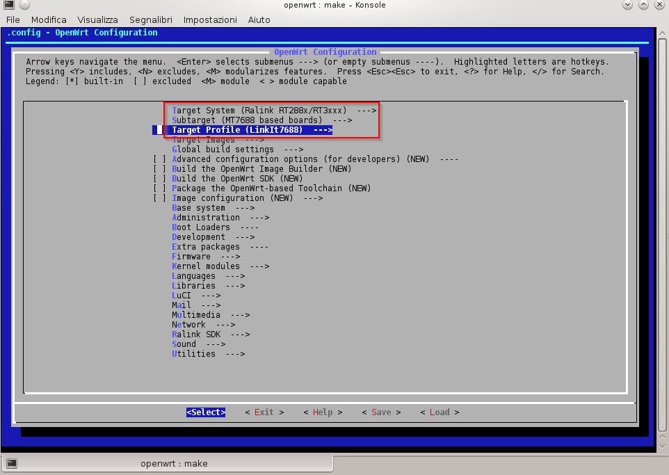
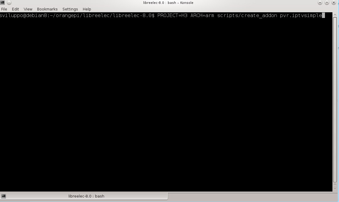
Linkit 7688 Duo Connections

and built the image

OpenWrt building for Linkit 7688 and 7688 Duo

we upload the image to the device.

Following the documentation availble at the link

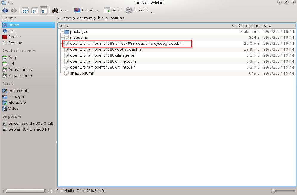
Update the firmware with a USB drive

to update the firmware copy the openwrt-ramips-mt7688-LinkIt7688-squashfs-sysupgrade.bin file to the root directory of a FAT32 USB drive and rename it as lks7688.img.

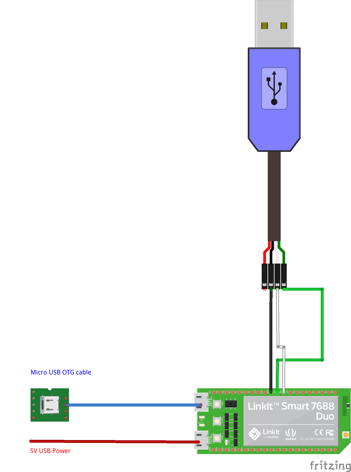
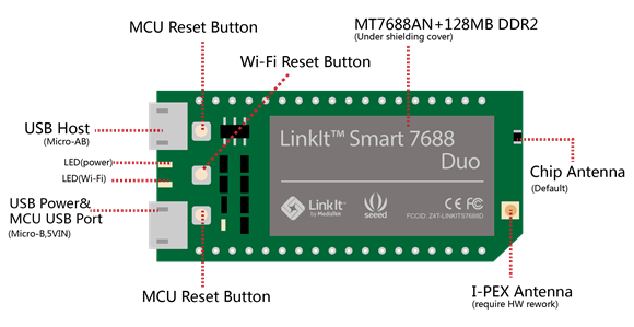
Attach, now,  the USB drive to the HOST port of the board with an OTG cable and follow the steps

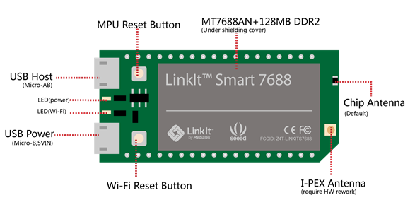
  1. Press and hold the on-board WiFi button.
  2. Press the MPU reset button once, while holding the WiFi button
  3. Keep holding the WiFi button for about 5 seconds. Do not release until the orange LED for WiFi is off.  DO NOT press the WiFi button longer than 20s or it will upgrade the bootloader.
  4. The device will automatically reboot after firmware update is complete.

aggiornamento7688duo

You can control the operation via the USB TTL serial connected to the PC and activated on the enabled Com port  with the following settings

  • Port:  Enabled COM
  • Speed: 57600
  • Data Bits: 8
  • Stop Bits: 1
  • Parity: None
  • Flow Control: XON/XOFF

putty-configuration
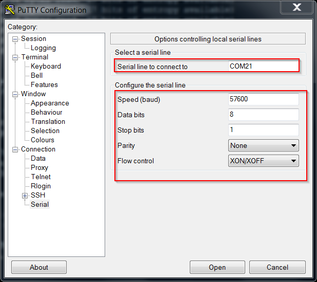
Use, for example, putty to connect, press Enter if the screen is not active,  and check the steps the system is runnig when upgrading

aggiornamento

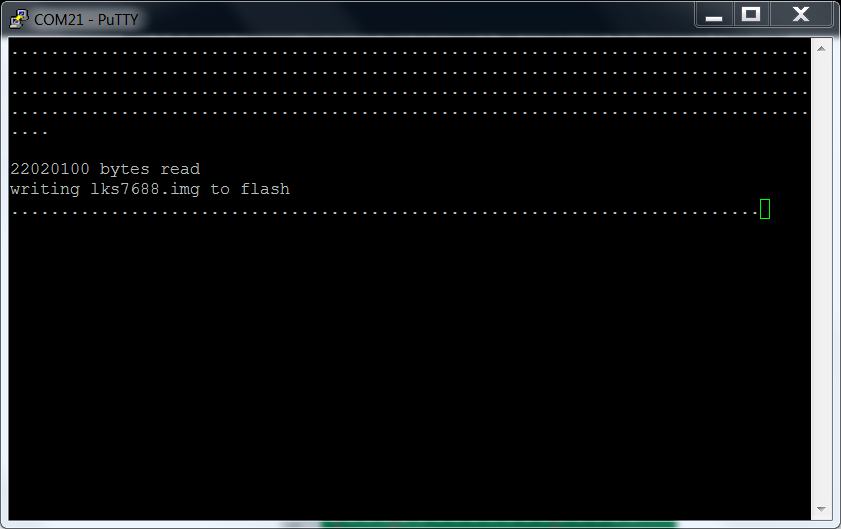
When the orange LED starts blinking at a lower frequency the card is ready to be used.

Search for visible access points from your PC  and you should find an access point named LinkIT_Smart_7688_xxxxxx, where xxxxxx identifies the specific device.

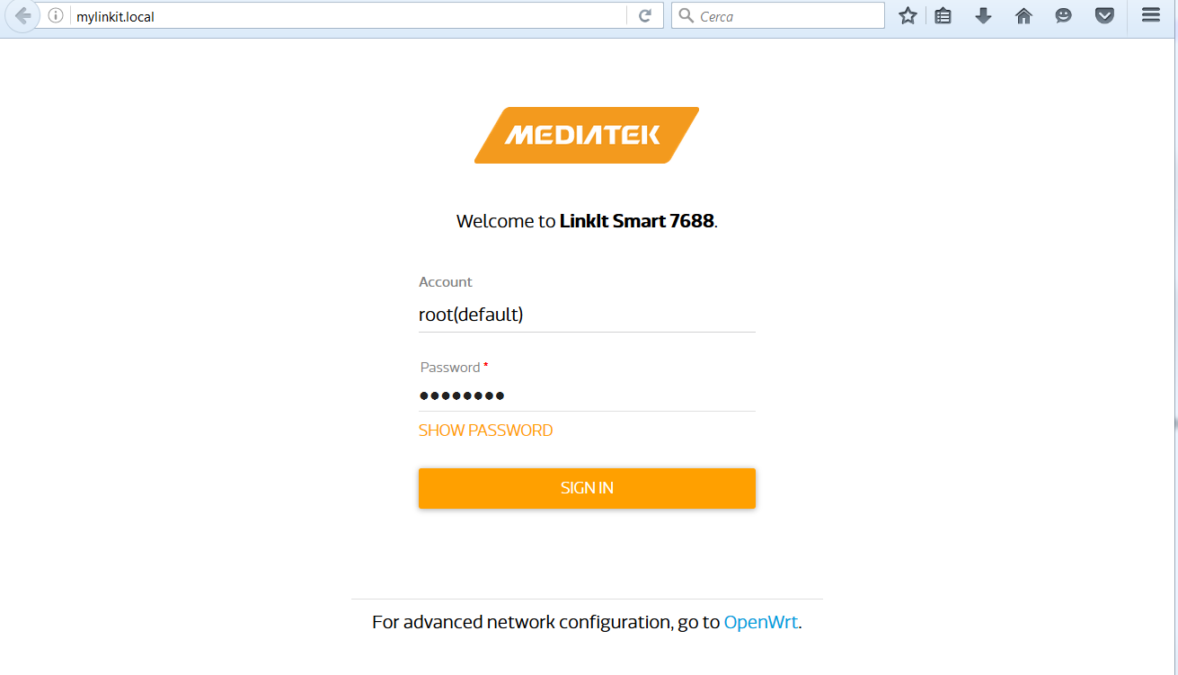
Connect to this Access Point and access via browser at 192.168.100.1 or at mylinkit.local if you have satisfied the prerequisites

Getting started

collegamentolinkit
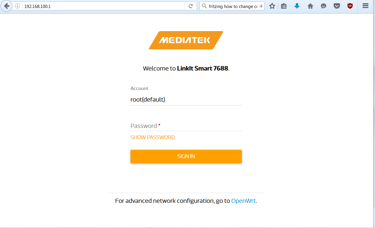
Enter a password and access the next step

collegamentolinkit2
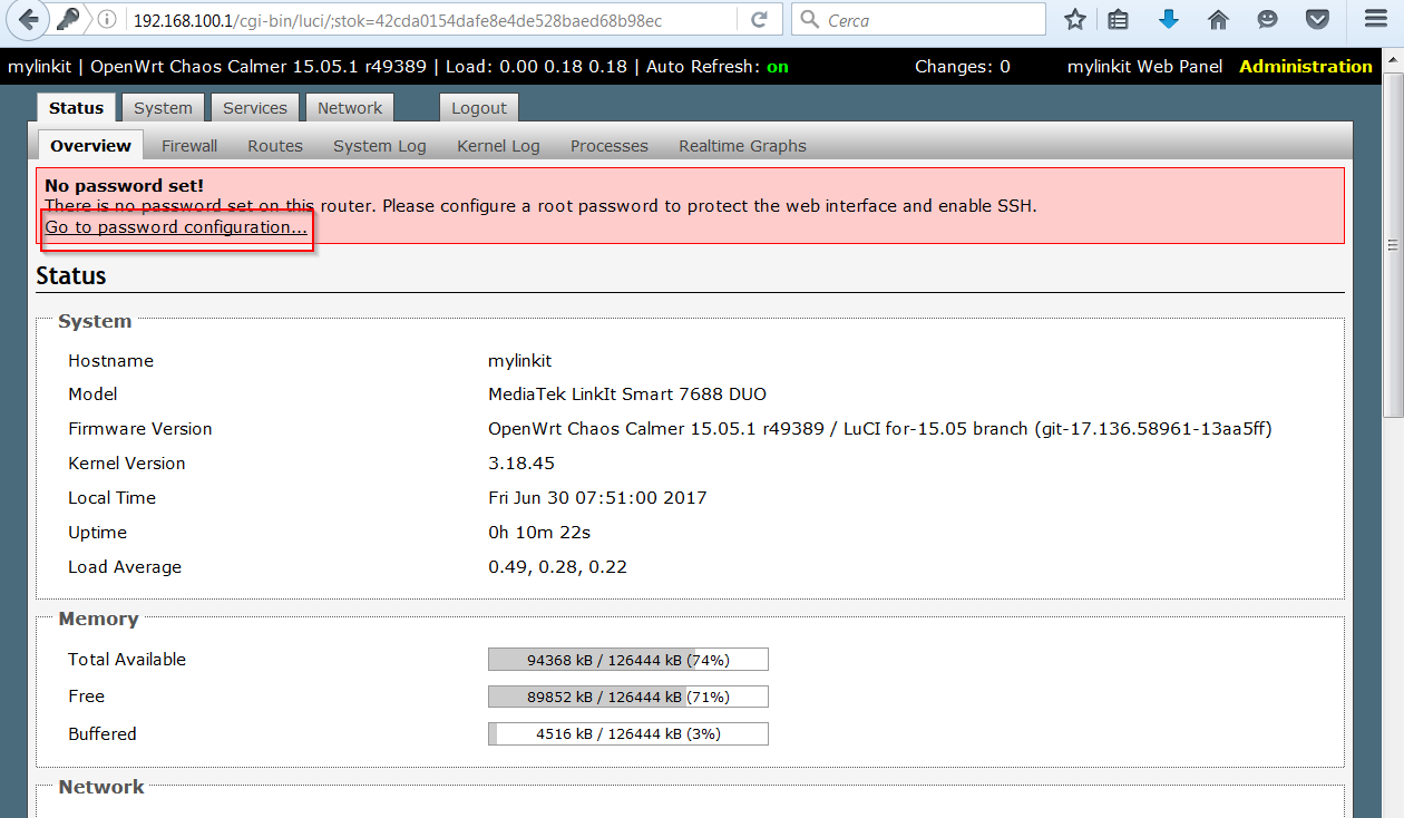
Select OpenWrt for Advanced Configuration

collegamentolinkit3
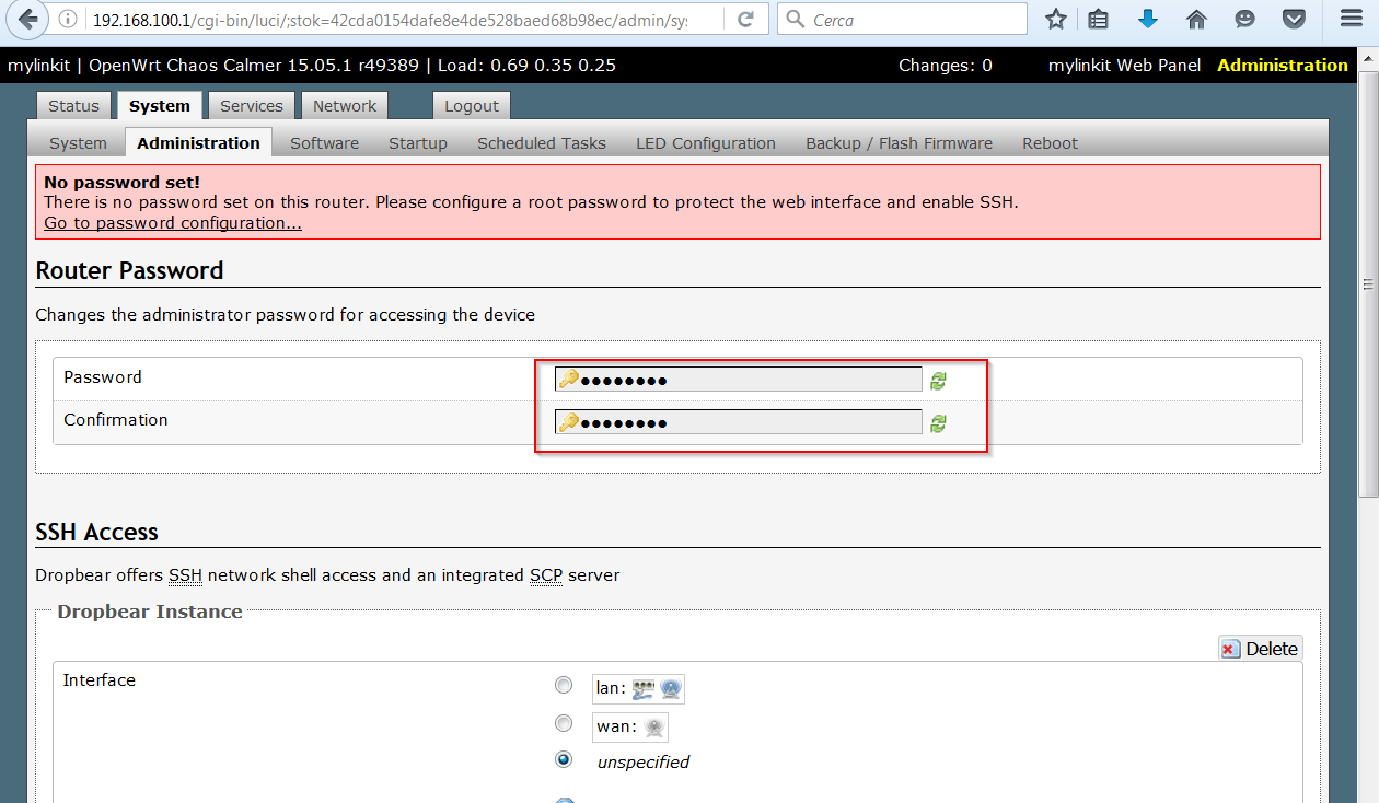
Set the password on OpenWrt

collegamentolinkit4entering it twice

collegamentolinkit5At this point, the system is configured as an Access Point. In our case, we wanted to set the Link 7688 Duo as a client of an Access Point with WPA2 security. To get this setting, if you have a visible network, go to the Network section of the main web console interface

accesso_linkit-smart_network1
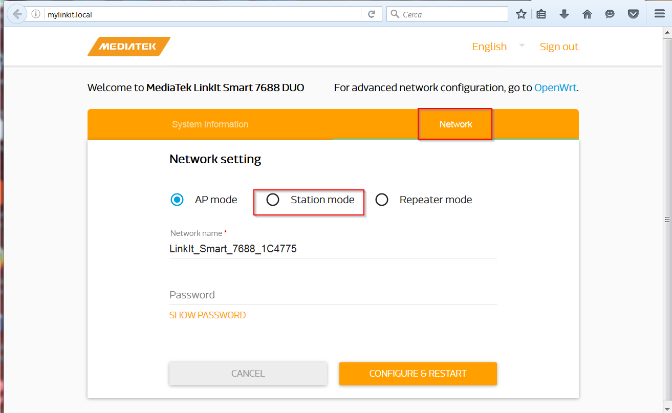
set the values for the Access Point and restart the system

accesso_linkit-smart_network2

If the Access Point is hidden, you should set the parameters directly in the configuration files in /etc /config.

Connect with putty to the previously connected USB TTL serial and  run the commands for Access Points with wpa2 security

 Save the settings

and activate the new configuration

Check the /etc/config/wireless file; you should see the addition of a new section, config wifi-iface ‘ap’,  to connect the board  to the access point

Now the card acts as a client and you can access it using the address released by the Access Point or by name as indicated by the documentation

Getting started

accesso_linkit-smartIn the next article, we’ll install and configure  the custom Lede firmware

Installation and configuration of Lede image on Linkit 7688 Duo

LEDE building for Linkit 7688 Duo

After OpenWrt image building using the Mediatek SDK

OpenWrt building for Linkit 7688 and 7688 Duo

this article describes how to generate a LEDE image for the Linkit 7688 Duo.

The steps on how to compile LEDE are available at the link

LEDE Building

Clone the code from the github in a shell command window,  always from the  Linkit folder

run

Create the src folder under Linkit and extract the compressed file

Feed for Linkit

This feed was created from Mediatek one, eliminating the binary drivers  dependency.

Copy the file to the src folder and uncompress it

Go to the Lede folder and copy the feeds.conf.default file  as feeds.conf

Run

Update the feeds  for the packages

Install the packages

Configure the kernel executing

Use the following settings

  • Target System: Mediatek Ralink MIPS
  • Subtarget: MT7688 based boards
  • Target Profile: Mediatek  LinkIt Smart 7688

menuconfigledeIn the Base system section enable mtk-linkit

mtk-linkitbasesystemSave and exit.

Run the building

where x is the number of cores to use in the building.

At the end of the process the generated image is available in the  bin/targets/ramips/mt7688/  folder as lede-ramips-mt7688-LinkIt7688-squashfs-sysupgrade.bin.

The built firmware is available here

Lede Image for Linkit 7688 Duo

WARNING: The image installation on the device is at your own risk. We accept no responsibility if the installation leads to  malfunction or block of the device.

If you upgrade the board using an usb key, you need to rename the lede-ramips-mt7688-LinkIt7688-squashfs-sysupgrade.bin file in lks7688.img.

This firmware may have malfunctions as it is not thoroughly tested and based on drivers under development.

In the next articles we’ll upload the images to the board and configure them

Installation and configuration of the Openwrt Image on Linkit 7688 and 7688 Duo

OpenWrt building for Linkit 7688 and 7688 Duo

After describing the general specifications of the two boards in the previous article

Linkit 7688 and 7688 Duo Development Boards

now we build the OpenWrt image from the sources. The following link describes the steps

Building the firmware from the source code

First we have to create the folder Linkit under /home/sviluppo in a shell command window in our Debian image, already used to  build OpenWrt in another article

Building OpenWrt Image

Install the prerequisites

Clone the OpenWrt repository

In the shell command window go to the openwrt folder and copy feeds.conf.default file as feeds.conf

Add the Mediatek feed for the boards

Update the feeds  for the packages

Install the packages

Configure the kernel executing

Use the following settings

  • Target System: Ralink RT288x/RT3xxx
  • Subtarget: MT7688 based boards
  • Target Profile: LinkIt7688

menuconfigSave and exit.

Run the building

At a certain point, the building generates an error for the wireless card libraries. Mediatek has not released the wireless card sources, but an sdk with compiled binaries for a kernel version  different from the one we are using in the building; the error reported is

One way to fix the problem is the following.

Go to the  /home/sviluppo/Linkit/openwrt/feeds/linkit/mtk-sdk-wifi/wifi_binary/  folder and copy the files for our kernel version

Rerun the building. At the end of the process the generated file is available in the  bin/ramips folder

linkit imageThe built firmware is available here

OpenWrt Linkit 7688 and 7688 Duo Image

WARNING: The image installation on the device is at your own risk. We accept no responsibility if the installation leads to  malfunction or block of the device.

If you upgrade the board using an usb flah drive, you need to rename the openwrt-ramips-mt7688-LinkIt7688-squashfs-sysupgrade.bin file in lks7688.img.

The image kernel for this building  is  3.18_45; If you want to use a recent kernel, you must use the opensource drivers available for the board; in the case of the Linkit 7688 Duo card, in our possession, we can rebuild the image using the Realtek rt76 drivers for the wireless network adapter and add the additional components for the Atmel MCU using LEDE, an OpenWrt fork

LEDE Project

In the next article you will build  a LEDE image for the Linkit 7688 Duo board. For the Linkit 7688 board at this time, the mraa libraries, used to interface the periphals, are not yet compatible with the latest version of LEDE and the functionality of the image is limited. There may be also bugs in the  wireless card opensource drivers, which hopefully are solved in the refinement of these drivers.

 LEDE building for Linkit 7688 Duo

Linkit 7688 Duo Connections

After the board specifications summary

Linkit 7688 and 7688 Duo Development Boards

this article describes how to connect to the board the following components that will be used later:

  • Micro USB OTG to the Host port
  •  USB  TTL Serial Device
  • 5 V power supply   to the port USB Power

The following diagram shows the connections to the board

Linkit connections

The table below shows the connections between the USB  TTL Serial device and the board

USB TTL PinLinkit Pin
RXUART_TXD2
TXUART_RXD2
GNDGND

In the netxt article we will show how to build the firmware for the Linkit 7688 and Linkit 7688 Duo

OpenWrt building for Linkit 7688 and 7688 Duo

Linkit 7688 and 7688 Duo Development Boards

This article briefly describes the Mediatek Linkit 7688 and 7688 Duo development boards. Below the links for the two boards

Linkit 7688

7688Linkit 7688 Duo

7688duo

The  specifications of the two boards are the following

Linkit 7688

ModelLinkit Smart 7688
MPUMT7688AN, MIPS24KEc, 580MHz
RAM128 Mb DDR2
Flash memory32 Mb
GPIO22 (MT7688AN) 3,3 V
PWM4 (MT7688AN) 3,3 V
Expernal Interrupts22 (MT7688AN)
SPI1 (MT7688AN)
UART Lite3 (MT7688AN)
PowerMicro USB 5V DC or PIN 3,3 V
USB HOSTMicro USB
EthernetBy extension
Wifi1T1R 802.11 b/g/n (2.4G)
User storareMicro SDSDXC sdcard
Dimensions55.7 x 26 mm
Weight39 grams

Linkit 7688 Duo

ModelLinkit Smart 7688 Duo
MPUMT7688AN, MIPS24KEc, 580MHz
MCUAtmel AVR 8MHz
RAM128 Mb DDR2
Flash memory32 Mb
GPIO3 (MT7688AN) 3,3 V
24 (ATmega32U4)
PWM8 (ATmega32U4) 3,3 V
External Interrupts8 (ATmega32U4)
SPI1 (ATmega32U4)
UART Lite1 (ATmega32U4)
1 (MT7688AN)
PowerMicro USB 5V DC or PIN 3,3 V
USB HOSTMicro USB
EthernetBy extension
Wifi1T1R 802.11 b/g/n (2.4G)
User storageMicro SDSDXC sdcard
Dimensions55.7 x 26 mm
Weight39 grams

The two boards share the same Microprocessor (MPU MT7688AN), but in the case of the Linkit 7688 Duo this MPU  is supported by the Atmel Microcontroller (MCU ATmega32U4) for device management.

The interfacing schemes are shown with peripherals in the two cases below

linkit_smart_7688lintit_smart_7688-duo

The operating system used for both bords is OpenWrt, but the peripherals management is different. While in the case of Linkit 7688 we only rely on MPUs and specific libraries to manage the interfacing with peripherals, for the Linkit 7688 Duo the ATmega32U4 microcontroller manages the peripherals. The programming  of the ATmega32U4 is executed with the Arduino IDE by adding the Linkit 7688 Duo board support into the tool as specified at the following link

Arduino Ide support for Linkit 7688 Duo

At the followning  link there is the Mediatek documentation for the two boards

Linkit 7688 and 7688 Duo Resources

The following pages  show how the two boards can interact with the various peripherals

Linkit 7688 peripherals

Linkit 7688 Duo peripherals

At the Mediatek site, there are also examples to follow step by step to test the various features of the development boards.

The next article shows how to connect the USB OTG cable , to use with a USB drive, an USB TTL serial cable,  to monitor the device,  to the board

 Linkit 7688 Duo Connections

Mqtt with Beaglebone and ESP8266 – Articles List

Below is a list of the  articles to follow  to build your IOT environment consisting of sensors and relays with Beaglebone, ESP8266 and MQTT Mosquitto server.

  1. Architecture and Mqtt protocol
  2. Mosquitto Mqtt installation on Beaglebone
  3. Mqtt on ESP8266
  4. Temperature sensor on ESP8266 with Mqtt protocol
  5. Relay on ESP8266 with Mqtt protocol
  6. Configuration of Http server, Mqtt websocket protocol on Beaglebone
  7. Freeboard dashboard installation and configuration on Beaglebone
  8. Android client to manage sensors with Mqtt protocol

Mqtt with Beaglebone and ESP8266 – Android Client

After Mosquitto server, ESP8266 nodes and Freeboard configuration

Mqtt with Beaglebone and ESP8266-Mosquitto installation on Beaglebone

MQTT with BeagleBone and ESP8266-MQTT ESP8266

MQTT with BeagleBone and ESP8266 – MQTT on ESP8266 with temperature sensor

MQTT with BeagleBone and ESP8266 – MQTT on ESP8266 with Relay

Mqtt with Beaglebone and ESP8266 – Freeboard

now we can proceed to use a Mqtt Client on an Android device.

In the Playstore various Mqtt applications are available

android mqttAfter the publishing and subscriber topics configuration in the Android client , analogous to what has been done for Freeboard widgets

Mqtt with Beaglebone and ESP8266 – Freeboard

it is possible to monitor the sensor temperature and humidity, the devices status and send commands to the relay (Turn On, Turn Off, Status, Restart, Sleep) and to the sensor (Restart, Sleep, Status).

Here is a screenshot with some subcriber topic and publisher topics of our installation using MQTT Dashboard

android mqtt relayoffWith the relay on

android mqtt relayon

Libreelec8 addon building for Orange PI PC

In the article about the Libreelec8 build for Orange PI PC

Libreelec8 in OrangePI PC

we created the environment and compiled the Libreelec8 image for our development board. We integrate what it has been said in the previous article showing how to build  the Libreelec 8 addons for our Orange PI PC board.

Now we proceed to build some addons. The packages that you can build are available in the kodi-binary-addons folder as shown below

libreelec8 addonsand in the packages/addons folder

addons packages

We build the  pvr.iptvsimple addon running the following command from the /home/sviluppo/orangepi/libreelec/libreelec-8.0 folder

addon command

We build the proftpd addon, among those avaliable in the packages/addons  folder

The compiled addons are available in the following folder

addons

Here are the links to download some compiled addons

PVR addons

Service Addons

Mqtt with Beaglebone and ESP8266 – Freeboard

After the Mqtt web client installation

MQTT with Beaglebone and ESP8266 – WebServer and MQTT WebSocket

let’s install now the dashboard freeboard

Freeboard

In a ssh commad shell go into the /var/www/html  folder on Beaglebone as root and clone the freeboard github respository; change the owner of the freeboard folder in www-data:www-data

With a web browser go to the freeboard  folder on Beaglebone webserver to access the dashboard

freeboard

We have to add now Freeboard additional plugins. We add the following

  •  freeboard-mqtt

Clone the https://github.com/alsm/freeboard-mqtt github

Download the mqtt paho javascript library

Paho mqtt javascript library

Here is the direct link to the library

Last Version mqttws31.js

Create the mqtt folder under the Freeboard plugins folder and copy the mqttws31.js and paho.mqtt.plugin.js files

Edit the paho.mqtt.plugin.js file and insert the reference to the mqttws31.js library in the external_scripts section; in this case too we have to change the folder and contents owner

Change the owner

Edit the /var/www/html/freeboard/index.html file and insert the reference to the paho.mqtt.plugin.js plugin in the heads.js section

  • Add the dynamic-highcharts plugin

Clone in a folder the github

Copy the plugin_highcharts.js to the folder /var/www/html/plugins/thirdparty and change the owner

Edit again the file /var/www/html/freeboard/index.html and add the plugin as done above

Access now the Freeboard dashboard and add the links to the temperature and humidity topics, the gauges and timeseries mesauring the values in real time and in a specific range of time . Here are some settings:

  • Datasource

freeboard datasource

  • Gauge

freeboard gauge

  • Timeseries

freeboard timeseriesChrome/Chromium browser allows to save the settings in a json file. This settings can be loaded locally or loaded from the web server, saving for example the dashboard.json file in /var/www/html/freeboard,  with the url

The image shows the Freeboad interface with various widgets showing the status and timeseries of the ESP8266 relay and sensors

freeboard dashboard

In these series of articles we configured the envinronment to access the Beaglebone using the beaglebone.local/beaglebone alias

Debian sd card setup for Beaglebone Black

but you can use anyway the Beaglebone IP tho access the services provided by the board.

In the next article we’ll treat the Mqtt Android client

Mqtt with Beaglebone and ESP8266 – Android Client


Libreelec8 in OrangePI PC

This article describes the steps that I ran to prepare a first version of Libreelec 8 in Orange PI PC cards and other H3 socs.

Starting from the Debian development envinronment, with its installed packages, already used for the compilation of OpenELEC 7

 Openelec compilation for Orange PI PC

we proceed to build an Libreelec 8 image.

We started as basis from the work done for Openelec 7 and Libreelec 7 available on the two github repositories

H3 Openelec 7 Github

H3 Libreelec 7 Github

Log in a unix command shell as user sviluppo; create a folder, libreelec , under orangepi folder and move into it

Clone the Libreelec8 github

The patches have been created for a specific version of the commit, so we align our github clone to that version

Download from the following link the patches, the H3 project and other stuff

H3 Libreelec 8

Unzip this file in /home/sviluppo/orangepi/libreelec

Run the following steps

1)Copy  to /home/sviluppo/orangepi/libreelec/libreelec-8.0/projects the folder

H3

2) Copy to /home/sviluppo/orangepi/libreelec/libreelec-8.0/packages/multimedia  the folders

cedarx
libmpeg2

3) Copy to /home/sviluppo/orangepi/libreelec/libreelec-8.0/packages/tools the folder

sunxi-tools

4) Copy to /home/sviluppo/orangepi/libreelec/libreelec-8.0/packages/sysutils  the folder

  sunxi-sys-utils

5) Copy to /home/sviluppo/orangepi/libreelec/libreelec-8.0/packages/graphics  the folder

sunxi-mali

6) Copy to /home/sviluppo/orangepi/libreelec/libreelec-8.0/packages/linux-drivers  the folder

mt7601u

7)  The following patches are available in /home/sviluppo/orangepi/libreelec/H3LE8/patches folder

linux.patch

image.patch

mkimage.patch

kodi.patch

libcec.patch

u-boot.patch

u-boot-release.patch

u-boot-update.patch

Patch the code from the /home/sviluppo/orangepi/libreelec folder running the following commands

Proceed to the image build for Orange PI PC from the folder /home/sviluppo/orangepi/libreelec/libreelec-8.0  running

At the end of the compilation in the /home/sviluppo/orangepi/libreelec/libreelec-8.0/target folder we find the files to install or update Libreelec 8

 At the link

Openelec 7 H3 FAQ

we find the boards we can build changing the SYSTEM parameter in the building command

SYSTEM=opi2
SYSTEM=opione
SYSTEM=opipc
SYSTEM=opiplus
SYSTEM=opilite
SYSTEM=opipcplus
SYSTEM=opiplus2e
SYSTEM=bpim2p
SYSTEM=bx2

This image is a first attempt to build Libreelec 8 for  H3  socs. The image was installed on Orange PI PC and the system worked well, but still bugs and malfunctions may occur.

Here is the built Libreelec 8 image for Orange PI PC

Orange PI PC Libreelec 8 Image

We tested this image on an Orange PI PC board.

Here are other images we did’t test on the devices

Orange Pi2 Libreelec 8 Image

Orange Pi Lite Libreelec 8 Image

Orange Pi One Libreelec 8 Image

Orange Pi PC Plus Libreelec 8 Image

Orange Pi Plus Libreelec 8 Image

Orange Pi Plus 2e Libreelec 8 Image

WARNING: The image installation on the device is at your own risk. We accept no responsibility if the installation leads to  malfunction or block of the device.

The following article shows how to build the addons

Libreelec 8 addon building for Orange PI PC