Category Archives: Configuration

MQTT with BeagleBone and ESP8266 – Mosquitto installation on Beaglebone

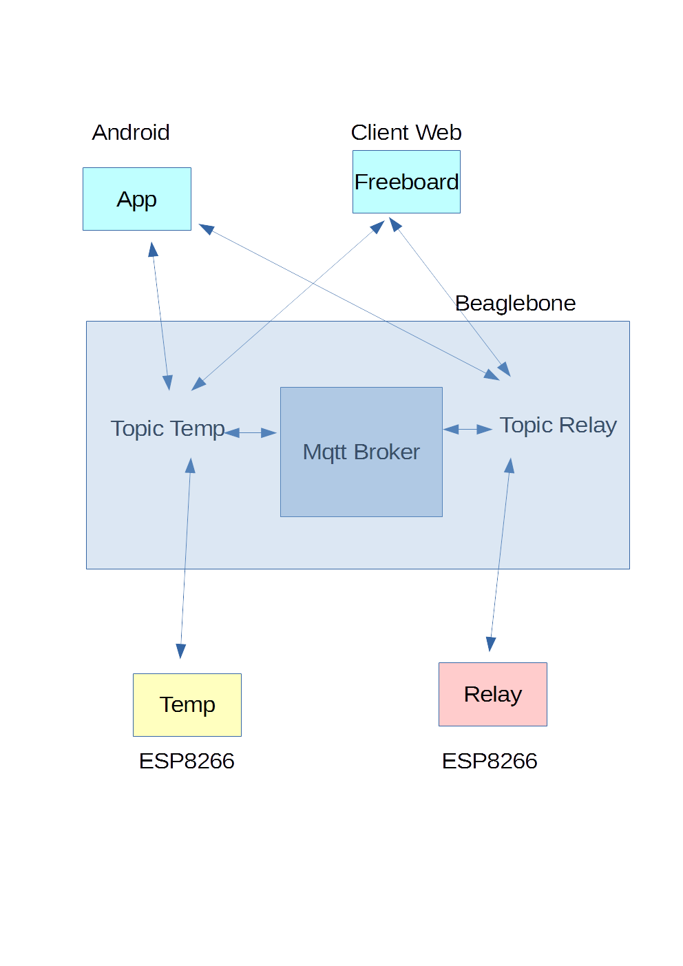
After summarizing the architecture that we are implementing in the previous article

 Mqtt with Beaglebone and ESP8266-Architecture

We proceed now with the installation of the MQTT broker on Beaglebone Black with the following version of Debian

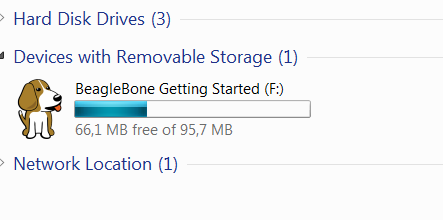
The image used is the following

Beaglebone Black Image

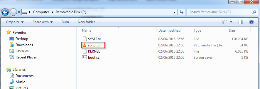
We proceed to the configuration as described in the article

Debian sd card setup for Beaglebone Black

Proceed to extend the space on the SD card  with the application gparted in a linux host or using the grow_partition.sh tool on BeagleBone in the /opt/scripts/tools folder

Performing the upgrade with this image we have  had space issue with 4Gb partition.

The message broker we’ll use is  mosquitto

Mosquitto

The version of Mosquitto with Debian Jessie  doesn’t not have the Wesockets services, which we’ll use for the Dashboard. For this reason, we have to install a more recent version of Mosquitto  (or recompile it from source).

Log on as root in a command shell on BeagleBone and add the Debian testing repository

Run the following

After the installation comment  the reference of the debian testing repository  in /etc/apt/sources.list

and run

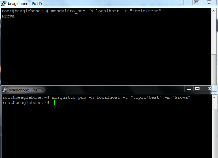
We test at this point if the server is installed correctly by running in a shell the subscription to a topic

In another command shell run the publishing on topic “topic / test”

The first shell has to show the message “Prova”

mqtt Test

With MQTT protocol we can define different QOS, as described in the  Mosquitto FAQ

QOS Mosquitto

With QoS = 0 the message is sent only once and is not required confirmation of receipt by the subscribers; the MQTT implementation in these articles is without protection with name/password or ssl channel encryption and with QOS=0.

In the next article we’ll proceed to the preparation of ESP9266 module with the Mqtt lua library inside the nodemcu firmware

MQTT with BeagleBone and ESP8266-MQTT ESP8266

Mqtt with Beaglebone and Esp8266-Architecture

In this series of articles we treat a MQTT message broker installed on  BeagleBone Black; this componet   allows  to manage various esp8266 devices, to which we connect various probes such as temperaure sensors, relays.

All this is handled with the help of apps on Android and a Dashboard installed on Apache on BeagleBone.

We start from the message MQTT broker (Message Queue Telemetry Transport); here there is the description of the protocol

MQTT

In particular in the FAQ section there are the first indications on the protocol and its use

MQTT Faq

The system is formed by three components:

  • MQTT Broker: relays the messages published to all subscribers.
  • Publisher: Publish messages in the registered topics on MQTT Broker.
  • Subscriber: Receives messages for its registered topics from MQTT Broker.

The following shows the topology for two topics used in our example

archThe system is composed of a MQTT  broker on BeagleBone. In this MQTT broker server you can define topics; different devices can be registered to these topics. For each topic the action can be subscription and publishing. By subscribing you receive all messages of topics, while with the publishing we can perform actions on the topic (for example, turn on a relay, restart a device, send sensor measurement,etc.). In the example we treat there will be, for example, a queue for the temperature monitor, hooked to esp8266 temperature reading device, another for the management of a relay, always run with esp8266. The MQTT broker relays the received messages among all  subscribers/ publishers for each topic.

We can subcribe/publish to the topics on the MQTT broker using  Android apps; the apps can receive messages and send commands to the esp8266 end device (Turn onRelay, Restart sensor, etc.).

With the javascript framework Freeboard

Freeboard

installed on the Beablebone Apache web server we can monitor in real time the end devices.

For more informations on MQTT system, consult the web site listed above.

In the next article we’ll start by installing the MQTT broker on BeagleBone Black

MQTT with BeagleBone and ESP8266 – Mosquitto installation on Beaglebone

Generating Images for BeagleBone with Omap Image Builder

This article describes how to proceed to the autonomous creation of an image for the BeagleBone Black /Green using the Omap Image Builder. In this specific example we create the image for the BeagleBone Black Rev. C.

The informations on the procedure to be followed are available on the site

Omap image builder

As a prerequisite to the creation of the image there is the need to perform the operations on arm hardware; with other systems it is possible to have issues. To this end, we will proceed to perform tasks on a  Orange PI PC with Armbian operating system. After preparing the Armbian system for Orange PI PC, as described in

Armbian Boot on Orange PI PC

log  in  ssh on Orange PI PC; in our case we used the sviluppo/password credentials

ssh on Orange PI PC

It is possible also to connect  by enabling Remote Desktop

Remote desktop setup for Armbian on Orange PI PC

Create a folder named beaglebone

Clone the code to create the image

The folder tree is the following

We proceed first to the creation of a standard Debian 8 image for Beaglebone Black

The task takes a long time and creates other folders including the deploy folder within which we will find the images. At the end go into deploy /image folder and run

Compress the created image with the command

To create a customized image proceed as follows:

  1. Go into the image-builder/configs folder and copy a configuration as base named custom-debian.conf. We have used as a base configuration bb.org-debian-jessie-lxqt-4gb-v4.1.conf. In custom-debian.conf add the following changes in  the deb_include section; as example we add the vsftpd server; change the chroot_script value too


    To exclude packages to be installed use the deb_exclude section. In the script are commented the various sections, among which we find those about  the definition of the hostname, passwords, user name creation, etc.
  2. Navigate to the image-builder/target/chroot folder and copy beagleboard.org-jessie.sh as custom-debian.sh.
  3. If you want to add python packages edit the custom-debian.sh file and add the other packages in install_pip_pkgs function

In this example we added only the ftp server. Go into the image-builder folder and run the command

The task  takes a long time. At the end access to the deploy/imagename folder and run

Compress the created image with the command

You can create now the micro sd card  with the FTP server available in the image  and the hostname changed in beagleboneblack.

The microSD burning  is already described in the article

Debian sdcard setup for Beaglebone Black

On Omap image builder site you’ll find other images types among which we highlight those for BeagleBone Black, Green, Iot, Machine Kit (image to manage Machinekit CNC machines), etc.

Startup of the Beaglebone development board

In a previous article we have given a brief description of Beaglebone Black board and its variants.

 Beaglebone development board

The BeagleBone in this review comes with 4GB of space on board, and with the operating system already installed.

We can access the BeagleBone, in our case the Black, without using the Ethernet network, but connecting it to a PC through the mini service USB connection as specified on the BeagleBone site

Getting started with Beaglebone

After connecting the BeagleBone Black to the PC via the USB cable we find  another removable  device to the existing disks

Beaglebone removable diskRunning start.htm we start an interface similar to the one available on  the  getting-started web site

getting startedWe proceed to the installation of network-over-USB drivers for the  operating system, Windows 64-bit in our case

driver network over usbProceed to download the file and run it, providing the permissions required by Windows

beaglebone driver installerAt the end the window with the performed operations is shown

beaglebone driver installer summaryUsing Firefox or Chrome we access to the following address http://192.168.7.2; we access in this way to the web server, running on Beaglebone board, through network over  USB

beaglebone web siteThe page shows how to update the system, login to the IDECloud9, perform various  Bonescript examples.

The access to the Cloud9 IDE

Cloud9 IDE Informations

takes place on port 3000 to the IP address specified above, ie http://192.168.7.2:3000

cloud9 ideIn our examples, we will not change the operating system present on the internal eMMC card but we will download an updated version of Debian for BeagleBone and will install it on a micro sd card.

The system can be closed  using  the Power button on board

power buttonor by connecting via ssh at 192.168.7.2 address with the debian user ,using temppwd as password, and executing the command “sudo poweroff”

sshIn the next article we will proceed to download and install on a micro sd card the last Debian image for BeagleBone

Debian sd card setup for Beaglebone Black

Remote control configuration for Libreelec on Amlogic Socs

In the previous article we installed on a microsd card Libreelec and started the device with this image

Libreelec Image for Amlogic socs

The remote control of the Beelink Minimx III is basic, so to have more keys  we decided to associate another remote control to the box.

We chose the following remote control that has more buttons included

remote control

According to this document on Amlogic site, although prepared in Chinese, through the use of online translators

How to change IR codes

It shows that the soc Amlogic natively manages the NEC protocol for remote controls and through remote.conf file we can associate the remote control code to the Linux system events. The map of the codes for the Linux system events is available in the header files of the Linux kernel

Input Event Codes

As a first step we log on Libreelec in ssh with root/libreelec. Copy the  /etc/amremote/libreelec.conf file as remote.conf in /storage/.config folder

and edit it as follows

Load the new codes of the remote file with the command

Press some button of the new remote control and run

In the case of compatible remote control we should see messages as shown below

The format is as follows: 0xAABBCCCC. Following Amlogic document linked above, the remote control code for a specific key is 0xBB; while defining the remote control code we have to use 0xCCCC0001. AA corresponds to the inverse logic of the command. In the case of the above example

BB = 0x51 = 01010001 in binary. The logical inverse = 10101110 in binary, which is just 0xAE.

AA = 0xAE. Binary = 10101110

The AA code is not used for our remote control configuration.

Press all the buttons on remote control and run the dmesg -c command. In our case we have the following codes

The mapping of the remote control in kodi is  in the /usr/share/kodi/system/keymaps/remote.xml file.

We mapped the remote control codes to the Linux input events. As an example let’s consider the Power button. The remote control code is

The KEY_POWER  event in the input-event-codes.h file is

We  created a link between the remote control code and the event in Linux in the  key_begin, key_end section of  the remote.conf file

Between the two data

insert a space, as indicated in Amlogic document linked above . The file used in this case is available at the following link

remote.conf

At the restart of the box Libreleelc reads the new configuration in /storage/.config/remote.conf  allowing so the use of the new remote control.

Remote desktop setup for Armbian on Orange PI PC

To enable the remote desktop for Armbian on Orange PI PC execute the logon to the system, for example using an ssh client

loginDelete, if installed, the packages

Install the following packages

Now we are able to login on Armbian using the remote desktop. Start the remote desktop client entering the Orange PI PC IP address

Remote Desktop ConnectionExecute the login with the user created at the first boot of Armbian, for example user1

Remote Desktop_LoginWe now have the access to the XFCE desktop remotely

Remote_Desktop

Armbian Boot on Orange PI PC

After the creation of the micro sd card with the Armbian image for Orange PI PC

Armbian image on micro sd

we can boot the Orange PI PC with the card inserted in the card slot. At the boot the first operation is the partition increase on the card, then the system requires the root password change from the default, 1234, to a new password. The next operation is the creation of a normal Debian user, for example user1; we provide the main required informations like username, password and letting the default  for the other fields. After these steps the system opens the XFCE graphical interface with the default resolution. To change the resolution execute the following command

It shows a list with all the available options; to enable a 1080p60 resolution execute

 To change the locales configuration execute the following command choosing the language to use

while to modify the keyboard layout use the following command

Resolution change of the video output in Openelec on Orange PI PC (Part2)

After the installation and compilation of the sunxi tools we are able to manage the script.bin file

http://www.microdev.it/wp/en/2016/07/29/resolution-change-of-the-video-output-in-openelec-on-orange-pi-pc-part1/

Copy into scriptfile folder our script.bin file.

From th sunxi link it is possible to view the guide about the parameters of the fex file

Fex Guide

Using the tool, compiled in part1 article, let’s convert the file from binary into a text one, executing the following command

Now we can work on the script.fex file. Edit it with a text tool software, for example pluma in Debian

script.fex

In this file we have to find the parameters to modify the video output; here are the parameters to modify

In our test file we found the following settings

According to the fex guide, for the HDMI output (screen_output_type=3) and a setting of 720p60 we have to change the 10 value into 5 in the screen0_output_mode parameter

WARNING: This file contains all the main parameters for the correct operation of the card. Don’t  change anything if you are not sure  waht the change of parameters entails.

After the parameters change convert the text file into a binary format with the following command, generating a .bin file

Move this file into the micro sd card; rename the original script.bin file into script.bin.back and move the  script720p60.bin into script.bin.

In the  Fex Guide we find all the parameters settings according to the various output resolutions.

Inserting the sd card into the Orange PI PC we can test the new output resolution connecting the hdmi to our television and powering on the card.

Resolution change of the video output in Openelec on Orange PI PC (Part1)

In the Orange PI Openelec image the default video output resolution is 1080p60. If our tv works with a different resolution we’ll have no image on the television.

To overcome this problem it is possible to change the resolution and fps  for the video output.

The micro sd has two partitions. We have to work in the vfat partition

schedasd

We have to modify the script.bin file.

contenutoschedasd

In the home partition of the debian user (sviluppo in our case) create a folder orangepi; inside this folder create another folder called  sunxi. Go into sunxi folder

Follow the instructions available from linux-sunxi site in order to modify the script.bin file. As first step install the required tools

Sunxi Tools

We have to install the libusb package, as described below

Install git and pkg-config

Now using git download the tool sources

Go into sunxi.tools folder

Execute the tools compilation

We are now able to modify the Orange PI PC parameters available in the script.bin file.

Create a folder under sunxi, for example scriptfile

Add to th ePATH variable the sunxi tools folders executables

Now in next article we can modify the parameters of video output in the script.bin file

http://www.microdev.it/wp/en/2016/07/29/resolution-change-of-the-video-output-in-openelec-on-orange-pi-pc-part2/

Debian envinronment for embedded systems development

In this article we describe Debian 8.5 installation we’ll use to compile Openelec for Orange Pi PC, Enigma2 images and other operations for embedded devices.

Download  AMD64  Debian 8.5 iso

Debian X86_64

Proceed with the operating system installation on your system. It is recommended  to use a virtual machine like VirtualBox. Use at least  4 GB of ram and 50 GB of hard disk.

VirtualBox

Using VirtualBox it is possible the virtual disk creation with dynamic space allocation. After the operating system installation log on into the system with the user created during the installation; we used the “sviluppo” user id. It is possible to log on to the linux system using the graphical interface or through ssh to the IP address of the Debian system.

Add to sudo group the user created in the Debian installation; open a shell command window and execute

In our case we have the following output

sviluppo user doesn’t belong to sudo group. Execute the command

Enter the root password when required and execute

In our example

Reboot the system

At the reboot log on into Debian and proceed to add the packages repositories, if not already present.  Go to the /etc/apt folder

Backup the original file

Edit the file using for example the vi editor

It is possible to comment out the lines positioning at the beginning of the line, press i to go in editing mode and add the # character. Pressing the ESC key we go into reading mode and it is possible to move in the file using the  arrow keys. In case of errors in editing mode it is possible to avoid the last change using the key ESC+u.

Comment out the  lines

Add the following lines

To add the lines press o keys to go into writing mode with an empty new line; with copy and paste we can add all the lines or proceed manually for each of them.

To save the file and quit press ESC+:wq.

It is possible to use one of the text editors available in Desktop Envinroment on which we logged into to edit and save the file.  For example to use pluma editor open a shell command windows and execute

From pluma open the file /etc/apt/sources.list, make the changes described above and save the file.

Update the repository lists  and the packages

Install the development packages

Install an ftp server to use for files transfer

After the installation open the file  /etc/vsftpd.conf and uncomment the following parameter

Open the file with vi or pluma as superuser

With vi editor search the string with the command

Delete the # character positioning the cursor on it and pressing the x key.

Save and quit with ESC+:wq.

Restart the ftp server using the command

We have now the envinronment to compile, modify, develop  our embedded systems.